Electric device and printing apparatus using the same

a printing apparatus and electric device technology, applied in the direction of instruments, visual presentations, computing, etc., can solve the problems of lowering the brightness of the leds, the insufficient time for light emission control of the leds, and the increase of the manufacturing cost of the electric device including a plurality of led lamps and switches, so as to reduce the cost of the apparatus. , the effect of simple configuration

Active Publication Date: 2014-01-02
CANON KK
View PDF1 Cites 3 Cited by
  • Summary
  • Abstract
  • Description
  • Claims
  • Application Information

AI Technical Summary

Benefits of technology

[0014]The invention is particularly advantageous since turn on control of light emitting elements such as LEDs, and switch press detection can be done by time-divisionally controlling the input and output of general purpose input / output ports while switching between their input and output operations without a dedicated logic circuit. This achieves a similar control operation with a configuration simpler than that in the conventional technique, thus contributing to a reduction in apparatus cost as well.
[0015]The present invention is also advantageous since it is possible to change the driving duties of a plurality of light emitting elements within the time-divisional driving period of the elements so as to change the light emission time of a specific light emitting element, or uniform the light emission times of a plurality of light emitting elements. Also, general purpose input / output ports are shared in light emitting element turn on / off control and switch key press detection to allow fine light emission control of the light emitting elements while achieving light emitting element turn on / off control and switch key press detection with a configuration simpler than that in the conventional technique.

Problems solved by technology

This raises the manufacturing cost of an electric device including a plurality of LED lamps and a plurality of switches.
Also, in the configuration of the above-mentioned conventional technique, because the LEDs are time-divisionally driven is performed, light emission control of the LEDs cannot be done for a sufficient time, thus lowering the brightnesses of the LEDs.

Method used


Image

  • Electric device and printing apparatus using the same
  • Electric device and printing apparatus using the same
  • Electric device and printing apparatus using the same

Examples


first embodiment

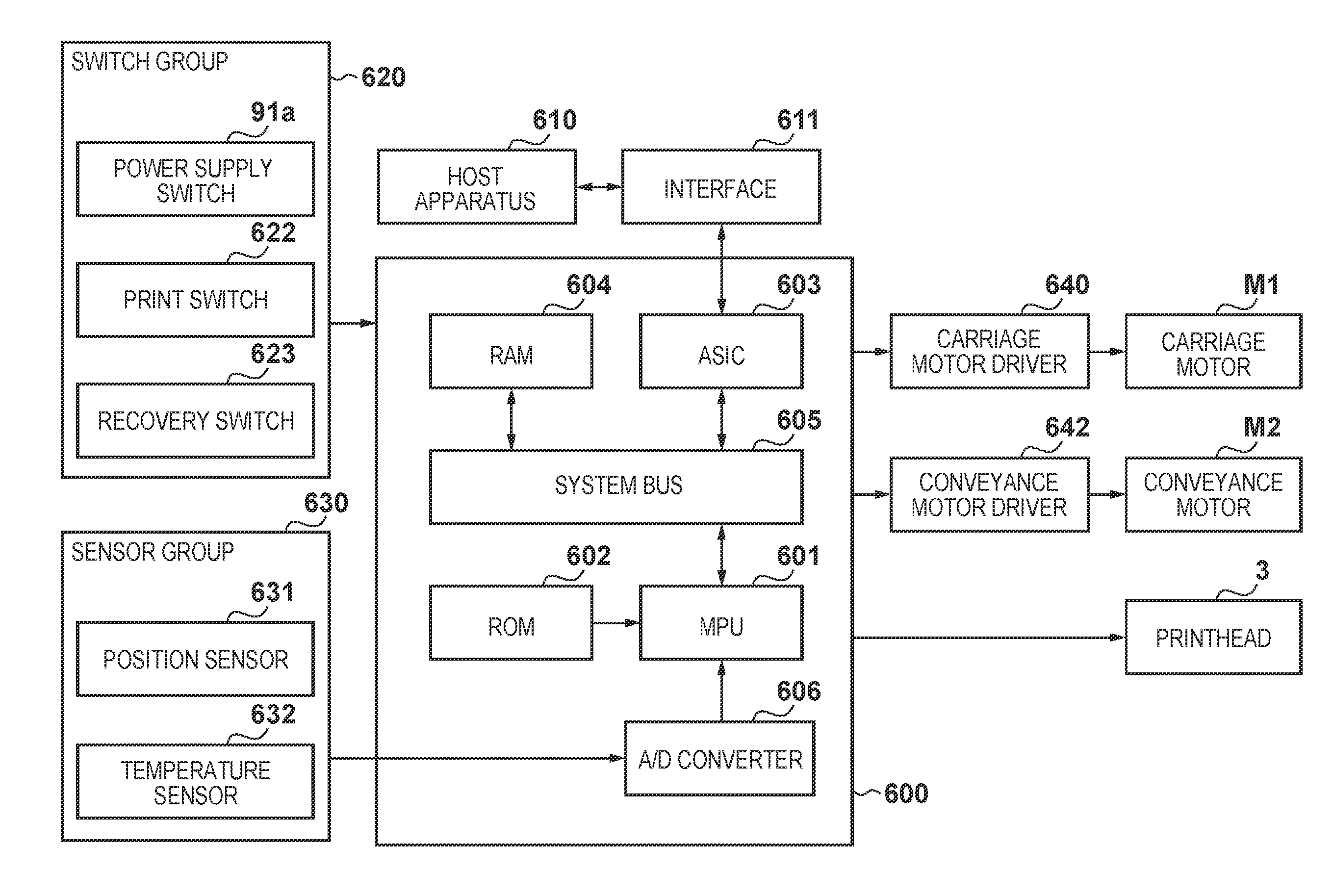
[0061]FIG. 4 is a block diagram showing the configuration of an electric device according to the first embodiment. Note that the same reference numerals as in FIG. 3 denote the same constituent elements in FIG. 4, and a description thereof will not be given.

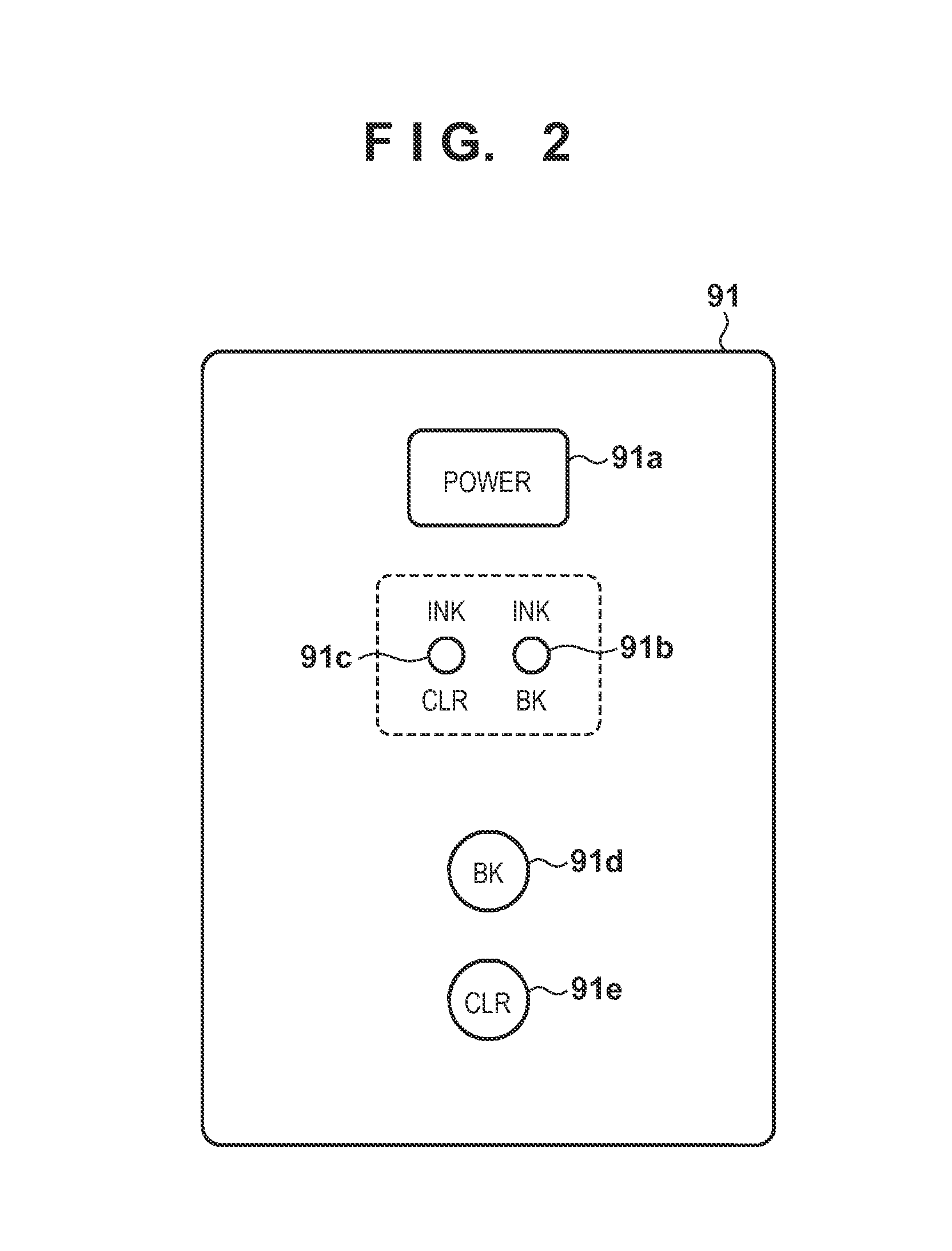
[0062]This electric device executes turn on control of two LEDs 91b and 91c (first and second LEDs) shown in FIG. 2, and key input control of two switches 91d and 91e (first and second switches) shown in FIG. 2.

[0063]This electric device is implemented only by switching of a general purpose input / output (GPIO) 608 by an MPU 601. That is, the general purpose input / output (GPIO) 608 is an input / output control circuit. The general purpose input / output (GPIO) 608 is connected to the MPU 601 via a system bus 605. The MPU 601 periodically performs a general purpose port switching process in a time period set in a timer (TIMER) 607. The MPU 601 sets a given value in a register (not shown) included in the general purpose input / output (GP...

second embodiment

[0085]An example of an electric device with a configuration which executes turn on control of four LEDs, and key input control of two switches will be described.

[0086]FIG. 6 is a block diagram showing the configuration of an electric device according to the second embodiment. Note that the same reference numerals as in FIGS. 3 and 4 denote the same constituent elements in FIG. 6, and a description thereof will not be given.

[0087]As can be seen from a comparison between FIGS. 6 and 4, LED2 and LED3 are added in this embodiment. These LEDs correspond to other LED lamps (not shown) provided in an operation unit 91. The anodes and cathodes of LED2 and LED3 are connected in directions opposite to those of the anodes and cathodes of LED0 and LED1, as shown in FIG. 6.

[0088]FIGS. 7A and 7B are tables showing a control sequence and a key press truth table.

[0089]The control sequence shown in FIG. 7A is obtained by adding turn on / off control of LED2 and LED3 to that shown in FIG. 5A according ...

third embodiment

[0093]An example of an electric device with a configuration which executes turn on control of two LEDs, and key input control of three switches will be described.

[0094]FIG. 8 is a block diagram showing the configuration of an electric device according to the third embodiment. Note that the same reference numerals as in FIGS. 3 and 4 denote the same constituent elements in FIG. 8, and a description thereof will not be given.

[0095]As can be seen from a comparison between FIGS. 8 and 4, one switch (KEY2) is added in this embodiment. This switch corresponds to another switch provided in an operation unit 91 and, for example, a switch 91a. As shown in FIG. 8, KEY2 is added between general purpose input / output port 2 (PORT2) and general purpose input / output port 3 (PORT3). Because the electric device according to this embodiment performs turn on control of two LEDs (LED0 and LED1), the turn on / off control is the same as in the first embodiment.

[0096]Key press detection of KEY2 can be real...


PUM


Abstract

An embodiment of this invention relates to an electric device capable of controlling a plurality of elements with an inexpensive, simple configuration, and a printing apparatus using the same. In this embodiment, an operation unit of the printing apparatus switches the states of a plurality of general purpose input/output ports between low-level signal output, high-level signal output, and input high impedance for each time set in a timer by an MPU. This allows LED light emission control and switch key press detection. Also, output ports used for LED light emission control, and input ports used for key press detection are shared using general purpose input/output ports to realize LED light emission control and switch key press detection with a configuration simpler than the conventional configuration.

Description

BACKGROUND OF THE INVENTION[0001]1. Field of the Invention[0002]The present invention relates to an electric device and a printing apparatus using the same and, particularly, to an electric device including, for example, a plurality of LED lamps and a plurality of switches, and a printing apparatus using the same as part of an operation unit.[0003]2. Description of the Related Art[0004]Operation units of various information processing apparatuses are provided with electric devices each including, for example, switches to be operated by the user, and LED lamps which notify the user of the apparatus operation states.[0005]Japanese Patent Laid-Open No. 2008-033915, for example, discloses a printing apparatus which prints on a print medium using a printhead, and its operation unit uses an electric device formed by an LED lamp and switch as well. Such an electric device normally has a plurality of LED lamps and a plurality of switches, which are controlled by, for example, a microcompute...

Claims


Application Information

Patent Timeline
Patent Type & Authority Applications(United States)
IPC IPC(8): B41J29/38
CPCB41J29/38B41J2/45G06K15/005
Inventor NAKA, HIRONORI
Owner CANON KK
Why Eureka
Try Eureka