Light source assembly, backlight module and liquid crystal display device

a technology of backlight module and light source assembly, which is applied in the direction of planar/plate-like light guides, lighting and heating apparatus, instruments, etc., can solve the problems of limited maximum divergent angle of light emitted by leds, non-uniform light emitted from backlight modules, and impaired performance of associated lcds

Inactive Publication Date: 2014-01-02
SYNERGY OPTOELECTRONICS SHENZHEN
View PDF3 Cites 13 Cited by
  • Summary
  • Abstract
  • Description
  • Claims
  • Application Information

AI Technical Summary

Problems solved by technology

However, the maximum divergent angle of light emitted by the LEDs is limited.
If the light incident surface is too close to the LEDs, some areas of the light incident surface between two adjacent LEDs may fail to receive the light and be relatively dark, causing the light emitted from the backlight module to be non-uniform and the performance of an associated LCD to be visibly impaired.

Method used


Image

  • Light source assembly, backlight module and liquid crystal display device
  • Light source assembly, backlight module and liquid crystal display device
  • Light source assembly, backlight module and liquid crystal display device

Examples


first embodiment

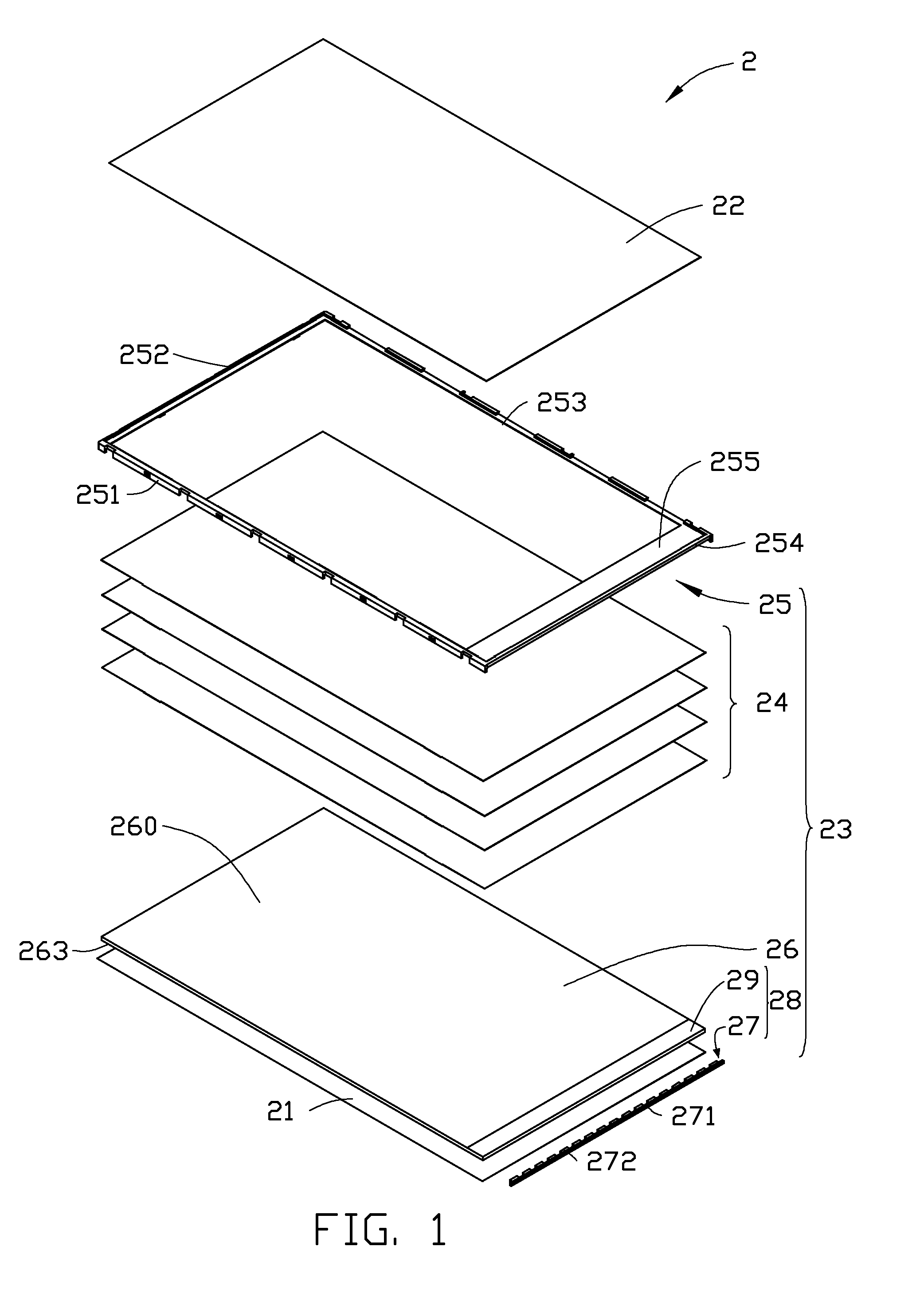
[0011]Referring to FIG. 1, in a first embodiment, a liquid crystal display 2 includes a liquid crystal panel 22 and a backlight module 23 providing light beams to the liquid crystal panel 22.

[0012]The backlight module 23 includes a number of optical films 24, a light guide plate 26, a light source assembly 28, a reflector 21, and a frame 25. The optical films 24, the light guide plate 26, the light source assembly 28, and the reflector 21 are received in the frame 25.

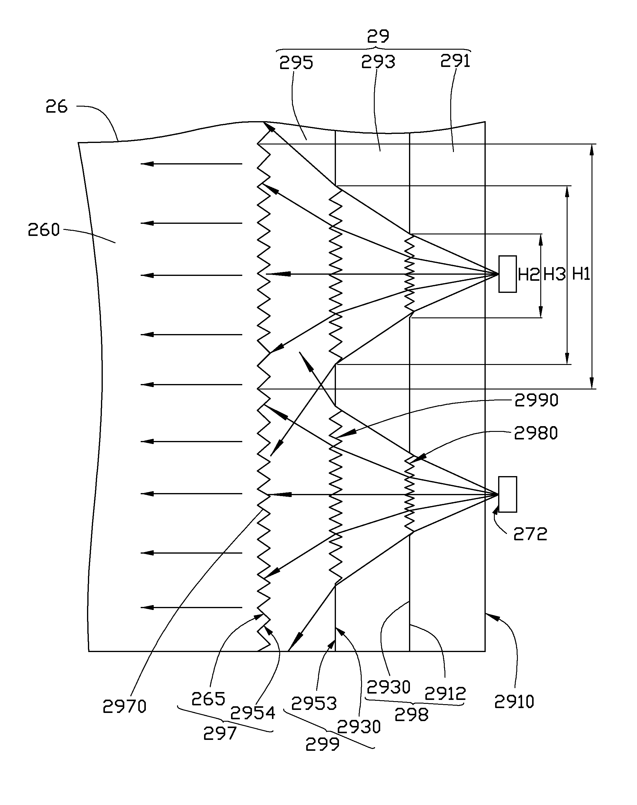
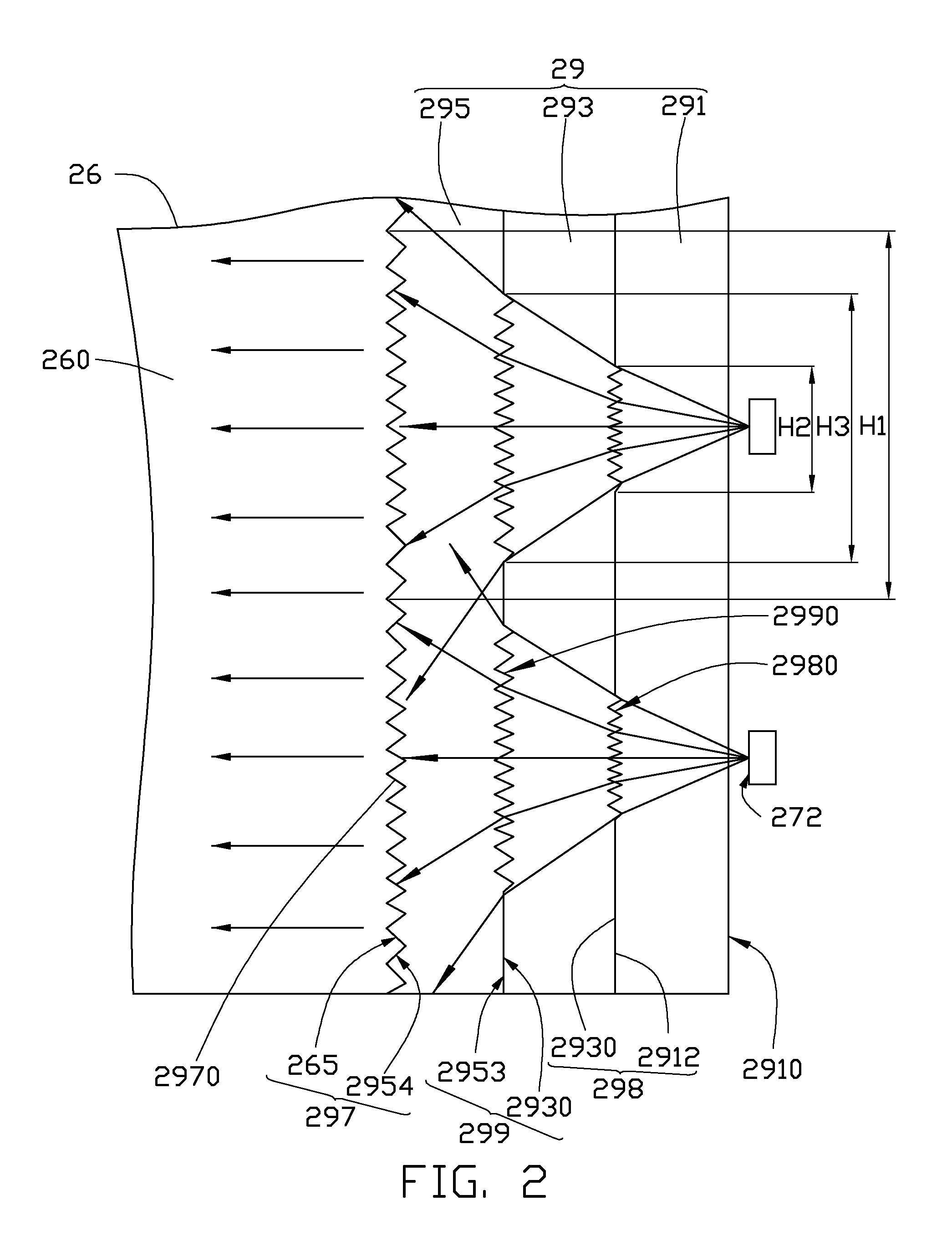
[0013]Referring also to FIG. 2, the light guide plate 26 includes a lateral light incident surface 265, a top light emitting surface 260 substantially perpendicular to the light incident surface 265, and a bottom surface 263 opposite to the top light emitting surface 260.

[0014]The light source assembly 28 faces toward the light incident surface 265 and includes a light source 27 and a diffusion member 29. The light source 27 includes a circuit board 271 and a number of LEDs 272 attached on the circuit board 271. Light b...

second embodiment

[0024]Referring to FIG. 3, a liquid crystal display 3 according to the present disclosure is shown. The structure of the liquid crystal display 3 is similar to that of the liquid crystal display 2, except that the structure of the diffusion member 39 is a two-layer structure. The diffusion member 39 only includes the first and second transparent layers 391 and 395. The second surface 3912 of the first transparent layer 391 and the third surface 3953 of the second transparent layer 395 form the first interface 398. The first interface 398 between the first transparent layer 391 and the interlayer 395 includes complementary first light diffusing microstructures 3980.

[0025]The first light diffusing structures 3980 diverge the light beams emitted from the respective LED, and the second light diffusing structures of the second interface between second transparent layer and the light guide plate diverge the light beams diverged by the first light diffusing structures 3980.

[0026]Distributi...


PUM

PropertyMeasurementUnit
transparentaaaaaaaaaa
refractive indexaaaaaaaaaa
light diffusing microstructuresaaaaaaaaaa

Abstract

A liquid crystal display includes a liquid crystal panel and a backlight module. The backlight module includes a light guide plate, a light source assembly, and a diffusion member. The diffusion member is disposed between LEDs of the light source assembly and a light incident surface of the light guide plate. The diffusion member includes a first transparent layer adjacent to the LEDs and a second transparent layer adjacent to the light guide plate. A refractive index of the first transparent layer is greater than that of the second transparent layer, and a refractive index of the second transparent layer is greater than that of the light guide plate.

Description

BACKGROUND[0001]1. Technical Field[0002]The present disclosure relates to a light source assembly with a diffusion member and a backlight module and a liquid crystal display using the light source assembly.[0003]2. Description of Related Art[0004]A typical liquid crystal display employs a number of light emitting diodes (LEDs) as a light source of a backlight module. The size of the backlight module can be reduced by decreasing the distance between the LEDs and a light incident surface of the light guide plate. However, the maximum divergent angle of light emitted by the LEDs is limited. If the light incident surface is too close to the LEDs, some areas of the light incident surface between two adjacent LEDs may fail to receive the light and be relatively dark, causing the light emitted from the backlight module to be non-uniform and the performance of an associated LCD to be visibly impaired.[0005]What is needed, therefore, is a means to overcome the described limitations.BRIEF DES...

Claims


Application Information

Patent Timeline
Patent Type & Authority Applications(United States)
IPC IPC(8): G02F1/1335G02B5/02F21V8/00
CPCG02F1/133615G02B6/0011G02B5/02G02B5/0236G02B5/0278G02B6/0016G02B6/0068G02B6/0073
Inventor HUANG, SIN-TUNGKANG, WUN-CI
Owner SYNERGY OPTOELECTRONICS SHENZHEN
Why Eureka
Try Eureka