
Optical time domain reflectometer systems and methods using wideband optical signals for suppressing beat noise

a reflectometer and optical signal technology, applied in the field of fiberoptic communication systems, can solve the problems of attenuation of signals, significant drawbacks of the foregoing otdr, and adversely affecting the performance of optical communication

Active Publication Date: 2014-01-02
ADTRAN
View PDF15 Cites 5 Cited by
  • Summary
  • Abstract
  • Description
  • Claims
  • Application Information

AI Technical Summary

Benefits of technology

The patent text describes a system for detecting anomalies in optical fiber communication systems using an optical time domain reflectometer (OTDR). The OTDR transmits a pulse along the fiber and measures the light returned from points along the fiber to detect any anomalies. However, the resolution of the OTDR is limited by the attenuation of the light as it travels along the fiber. The patent proposes a correlation OTDR system that can improve the resolution and range of the OTDR by independently varying the parameters that control range and resolution. The patent also discusses techniques for improving the quality of the optical returns in the OTDR system, such as using a wider bandwidth laser and reducing noise in the optical channel.

Problems solved by technology

However, anomalies along an optical fiber, such as degraded splices, can adversely affect the performance of optical communication.
Unfortunately, there are several significant drawbacks associated with the foregoing OTDR.
However, the signal is attenuated as it travels along the optical fiber limiting the useful range of the pulse.
A longer pulse of any given amplitude has more light energy and, therefore, a longer range but degrades resolution.
Noise in the optical channel affects the quality of the OTDR returns and ultimately the OTDR test results.

Method used


Image

  • Optical time domain reflectometer systems and methods using wideband optical signals for suppressing beat noise
  • Optical time domain reflectometer systems and methods using wideband optical signals for suppressing beat noise
  • Optical time domain reflectometer systems and methods using wideband optical signals for suppressing beat noise

Examples


Embodiment Construction

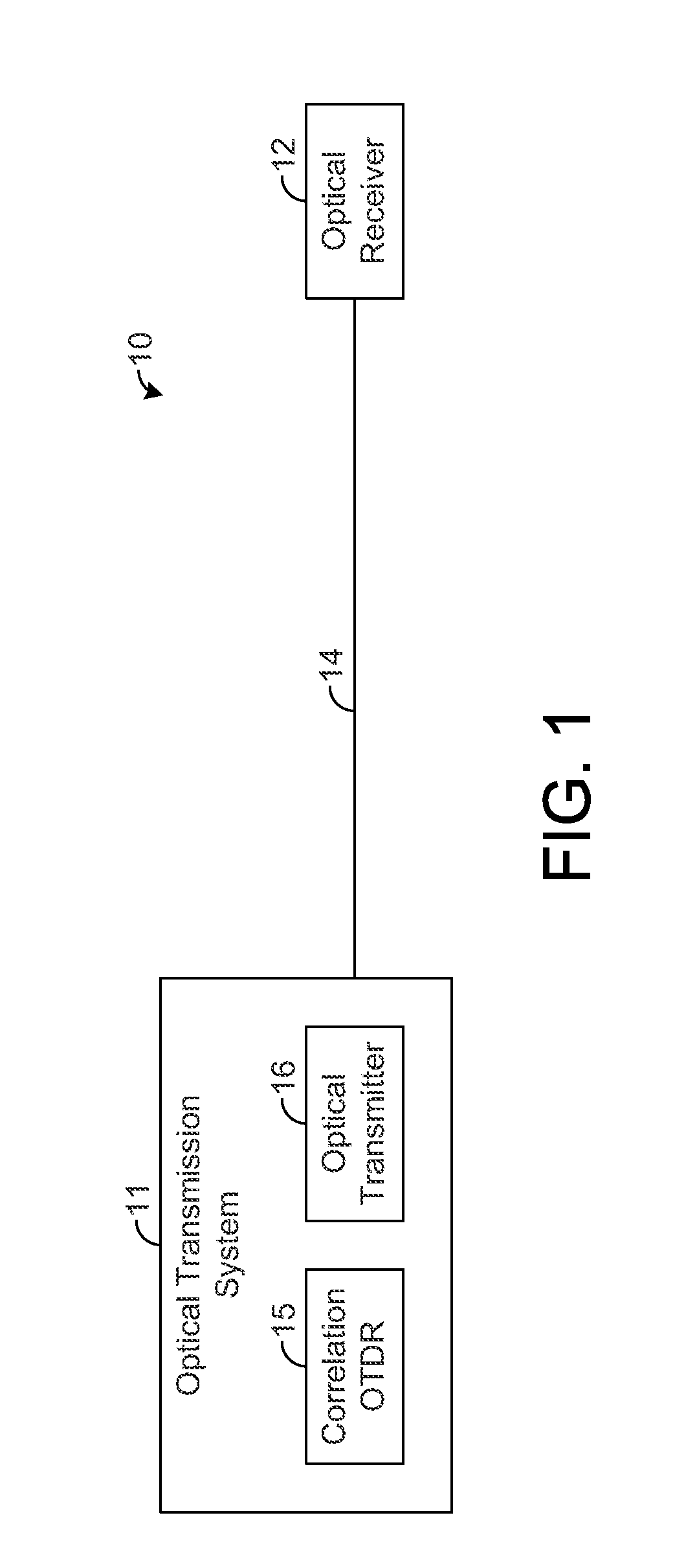
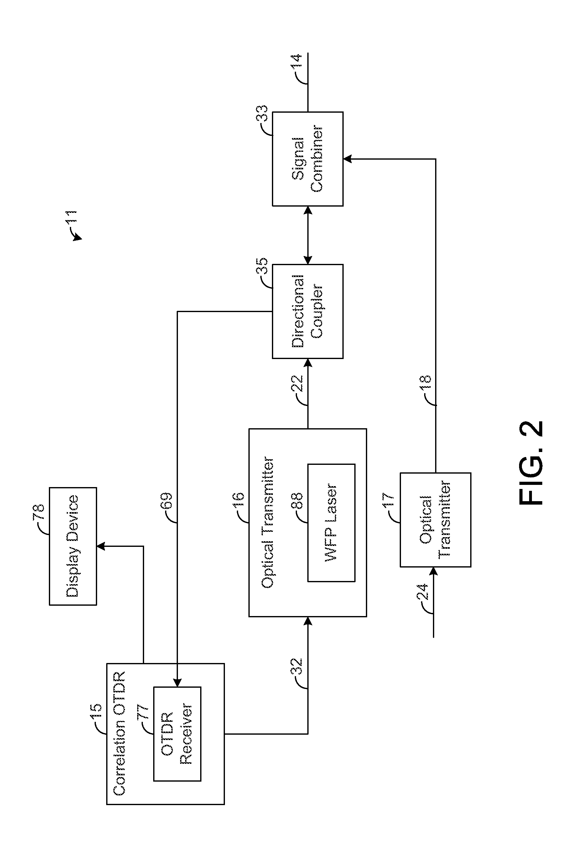
[0017]The present disclosure generally pertains to systems and methods for reducing beat noise in correlation optical time domain reflectometers (“correlation OTDRs”). As described above, a correlation OTDR provides a correlation sequence (e.g., PN sequence) that is continuously transmitted along an optical fiber during testing. Such continuous transmission can result in beat noise that degrades the quality of the measured returns. In this regard, each sample is composed of backscatter returns from many points along the fiber that arrive at the OTDR at the same time. When a subset of these returns have frequency differences that appear the passband of the OTDR receiver, the constructive and destructive interference of these returns at the OTDR receiver can cause significant low-frequency beat noise in the OTDR signal. Increasing the spectral width of the transmitted signal reduces the impact of beat-notes in the OTDR receiver by spreading the power of the beat-notes outside of the r...


PUM


Abstract

A correlation optical time domain reflectometer (OTDR) provides a correlation sequence that is continuously transmitted along a fiber for testing the fiber for anomalies. Such continuous transmission can result in beat noise that degrades the quality of the measured returns. In this regard, each sample is composed of backscatter returns from many points along the fiber that arrive at the OTDR at the same time. When a subset of these returns have frequency differences that appear in the passband of the OTDR receiver, the constructive and destructive interference of these returns at the OTDR receiver can cause significant low-frequency beat noise in the OTDR signal. An optical transmitter is configured to transmit the correlation sequence through the fiber using a wideband optical signal such that the beat noise is suppressed within the passband of the OTDR receiver, thereby improving the quality of the returns measured by the OTDR.

Description

CROSS REFERENCE TO RELATED APPLICATION[0001]This application claims priority to U.S. Provisional Application No. 61 / 661,705, entitled “Systems and Methods for Reducing Inter-Pulse Coherent Rayleigh Noise in Optical Time Domain Reflectometers” and filed on Jun. 19, 2012, which is incorporated herein by reference.RELATED ART[0002]In fiber-optic communication systems, optical signals are used to carry data sometimes across great distances. It is well known that optical signals typically provide significantly higher data rates than those enabled by electrical signals. However, anomalies along an optical fiber, such as degraded splices, can adversely affect the performance of optical communication. Thus, techniques have been developed to locate fiber anomalies so that the anomalies can be repaired in order to improve communication performance.[0003]In particular, optical time domain reflectometers (OTDRs) for detecting optical fiber anomalies have been developed and successfully used. On...

Claims


Application Information

Patent Timeline
Patent Type & Authority Applications(United States)
IPC IPC(8): H04B10/2507
CPCH04B10/2507G01M11/3118H04B10/071
Inventor JOFFE, DANIEL M.SANDSTROM, LEIFBEKKEN, GEORGE ELLIOTT
Owner ADTRAN
Learn More