Fuel injector

a fuel injector and fuel technology, applied in the direction of magnets, machines/engines, magnets, etc., can solve the problems of affecting the overall unfavorable functional properties, entail significant added manufacturing costs, and extremely small outer diameter, and achieve the effect of greatly increasing the dfr rang

Active Publication Date: 2014-01-09
ROBERT BOSCH GMBH
View PDF0 Cites 6 Cited by
  • Summary
  • Abstract
  • Description
  • Claims
  • Application Information

AI Technical Summary

Benefits of technology

[0008]It is particularly advantageous that with the aid of the dimensioning of the example fuel injector according to the present inve

Problems solved by technology

However, the positive aspect of a very high electrical resistance which results is offset by an extremely high magnetic resistance which is reflected in a considerable loss of power, and which thus determines the overall unfavorable functional properties.
As a result, however, suc

Method used


Image

  • Fuel injector
  • Fuel injector
  • Fuel injector

Examples


Embodiment Construction

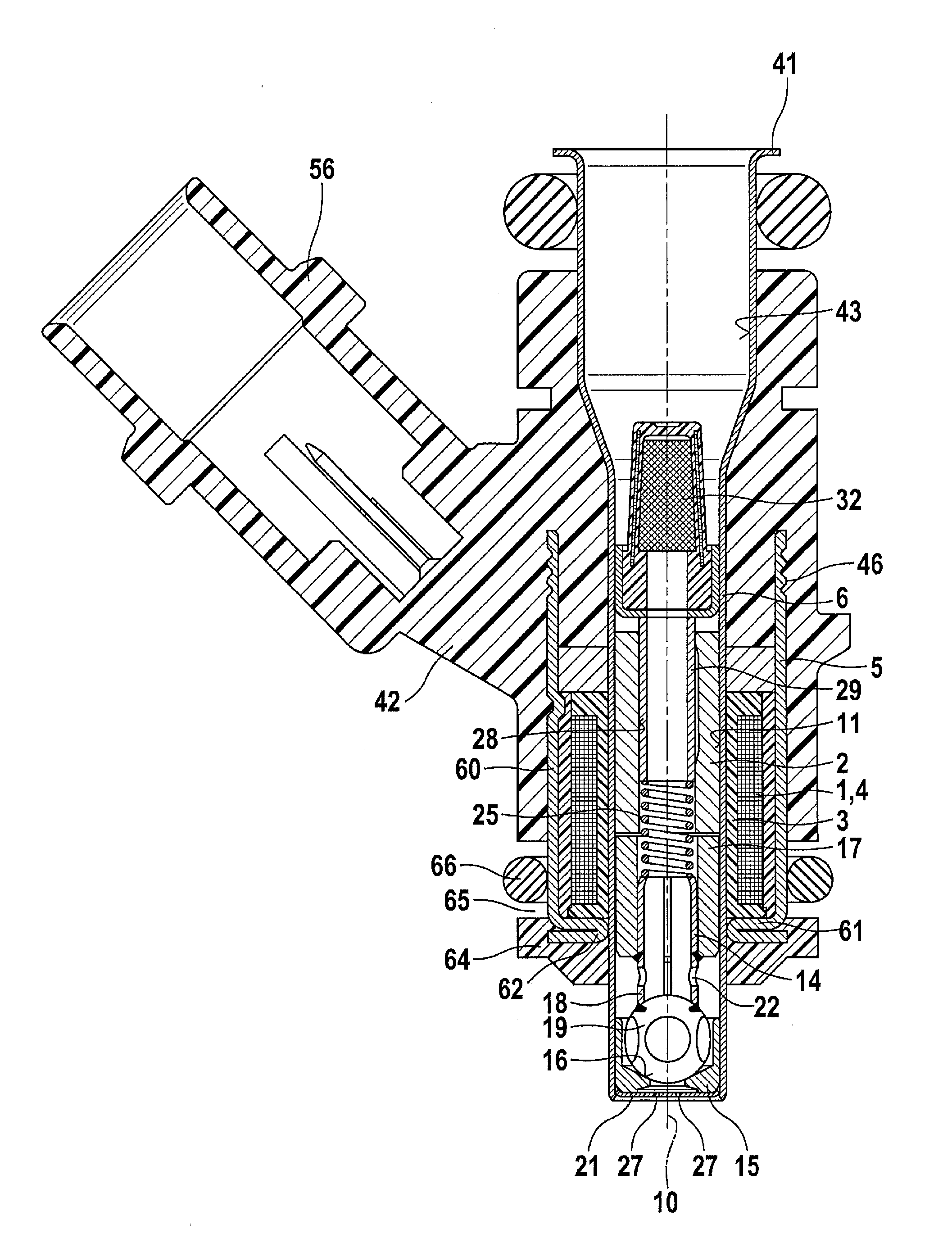
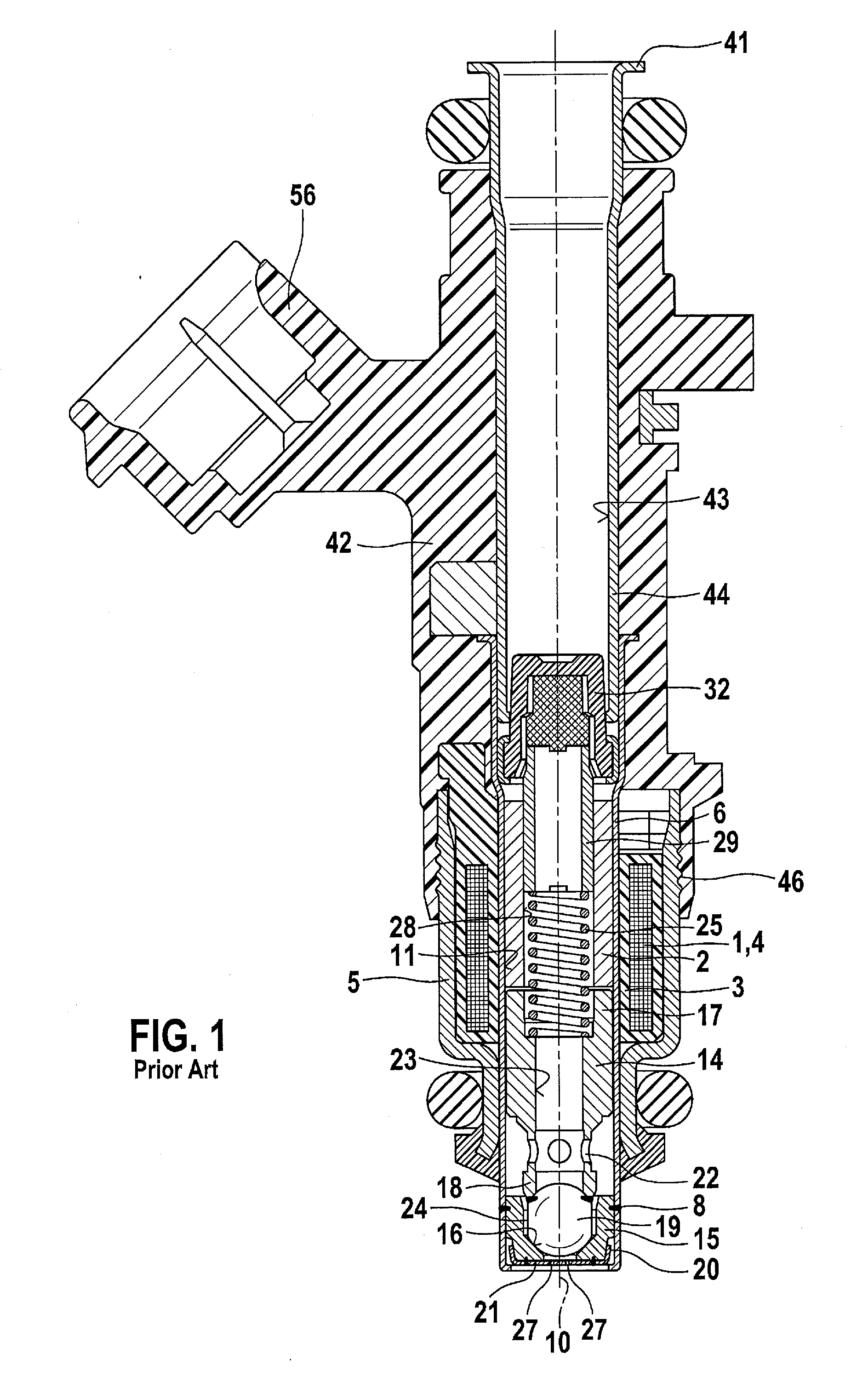
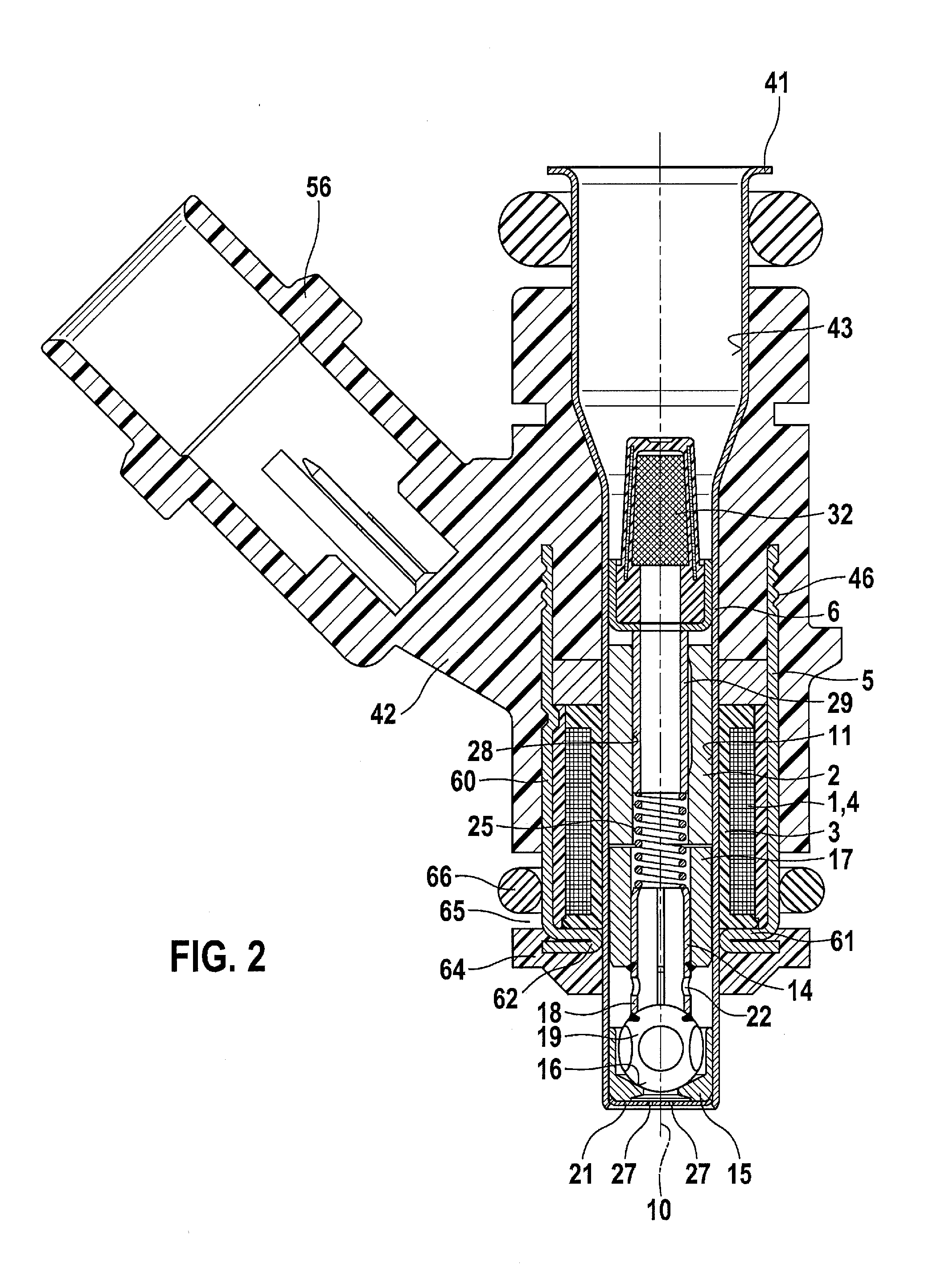
[0013]For a better understanding of the present invention, FIG. 1 illustrates one example of an electromagnetically activatable valve in the form of a conventional fuel injector for fuel injection systems of mixture-compressing, spark ignition internal combustion engines.

[0014]The valve has a largely tubular core 2 which is enclosed by a solenoid 1 and which is used as an internal pole and in part for the flowthrough of fuel. Solenoid 1 is completely enclosed in the peripheral direction by an outer, for example ferromagnetic, valve casing 5 having a sleeve-shaped and stepped design, and which represents an external magnetic circuit which acts as an external pole. Solenoid 1, core 2, and valve casing 5 together form an electrically energizable actuating element.

[0015]While solenoid 1, embedded in a coil former 3, externally surrounds valve sleeve 6 with a winding 4, core 2 is introduced into an internal opening 11 in valve sleeve 6 which extends concentrically with respect to a valve...


PUM


Abstract

A fuel injector for fuel injection systems of internal combustion engines. The valve includes an electromagnetic actuating element which has a solenoid, a solid core, an external magnetic circuit component, and a movable armature for activating a valve closing member which cooperates with a valve seat surface provided on a valve seat member. The valve has extremely small outer dimensions. By optimizing the dimensions of the electromagnetic circuit, the outer diameter of the external magnetic circuit component in the peripheral area of the solenoid is 10.5 mm<DM<13.5 mm. This increases the flexibility in installing fuel injectors having different valve lengths, which are made possible due to the special modular design. The valve is suitable as a fuel injector in particular for use in fuel injection systems of mixture-compressing, spark ignition internal combustion engines.

Description

FIELD[0001]The present invention is directed to a fuel injector.[0002]BACKGROUND INFORMATION[0003]A fuel injector is described in German Patent No. DE 38 25 134 A1 which includes an electromagnetic actuating element having a solenoid, an internal pole, and an external magnetic circuit component, and a movable valve closing member which cooperates with a valve seat associated with a valve seat member. The injector is enclosed by a plastic extrusion molding, which extends primarily in the axial direction and encloses the connector which acts as the internal pole, and the solenoid. Ferromagnetic fillers which conduct magnetic field lines are introduced into the plastic casing, at least in the area enclosing the solenoid. In this regard, the fillers enclose the solenoid in the peripheral direction. The fillers are fine-grained crushed particles of metals having soft magnetic properties. The small metal particles which are magnetically embedded in the plastic have a more or less globular...

Claims


Application Information

Patent Timeline
IPC IPC(8): F02M51/06
CPCF02M51/0625F02M51/0682F02M2200/08F02M2200/9061H01F7/1607F02M63/0019
Inventor GRANER, JUERGENMAIER, MARTINRIEG, BERNDSOHM, VOLKERLANDER, JUERGENMIZOBE, TAKUYA
Owner ROBERT BOSCH GMBH
Why Eureka
Try Eureka