

Mill
- Summary
- Abstract
- Description
- Claims
- Application Information
AI Technical Summary
Benefits of technology
Problems solved by technology
Method used
Image

Examples
examples
[0103]Hereinafter, the examples of the mill according to the present invention are shown in order to clarify effects of the present invention. However, the present invention is not limited to the following examples.
Manufacture of Recycled Fine Aggregate for Concretes
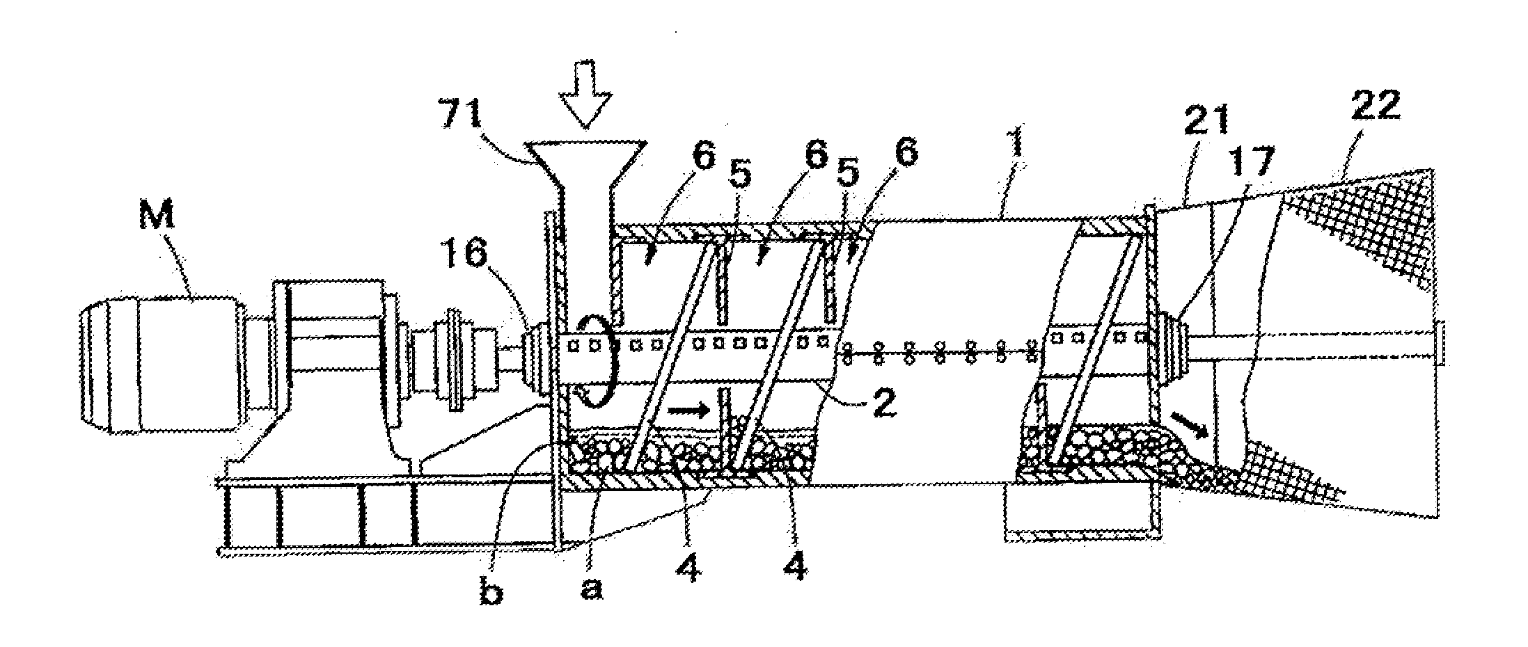
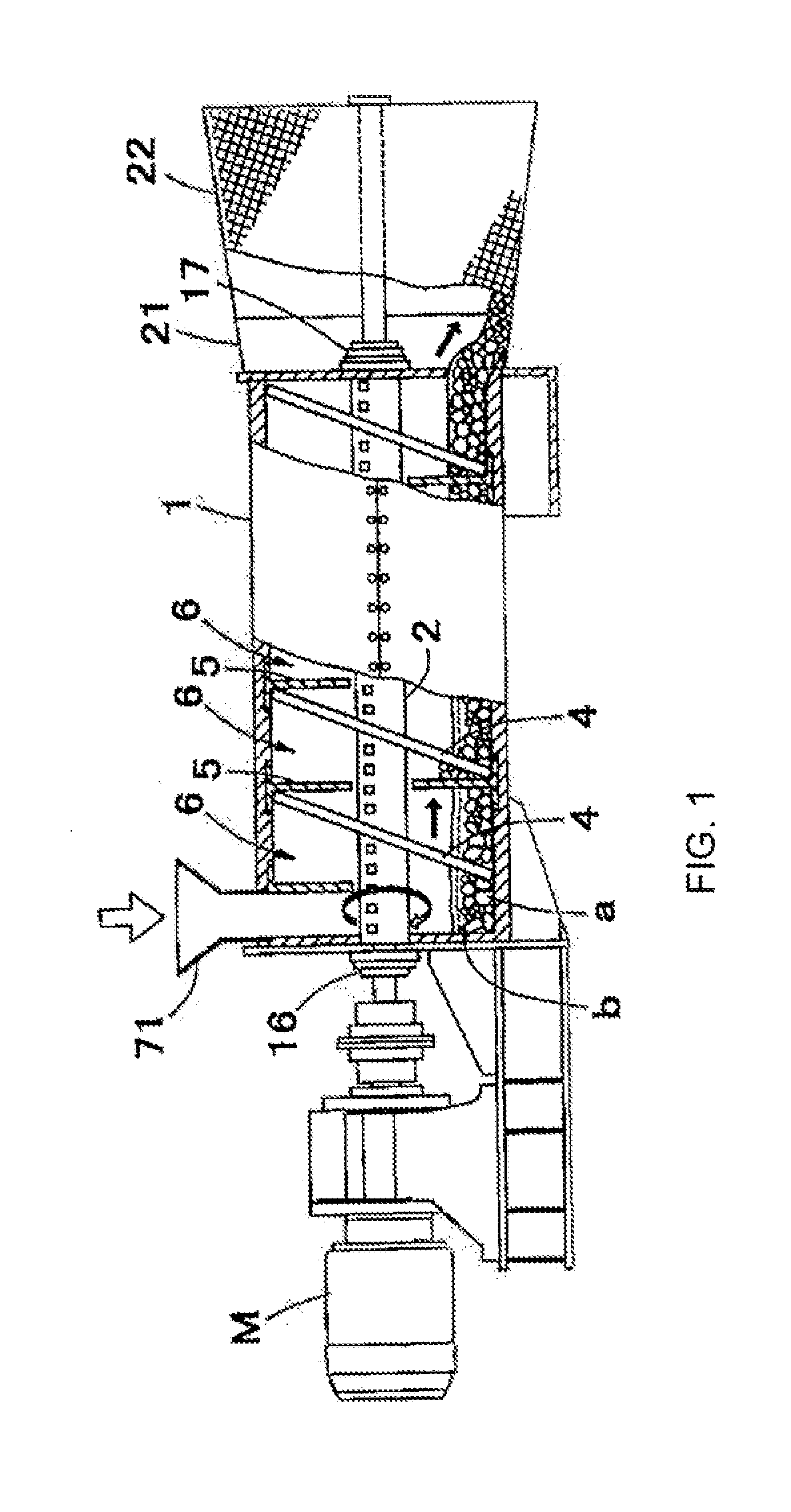
[0104]A milling process of concrete scrap materials (concrete shells) was conducted using the mill of the second embodiment (FIG. 11-FIG. 16), in order to study properties of the aggregate after the milling process. Results are shown in the following tables. As shown in the following tables, the aggregate after milling process satisfied the standard values of JIS in all test items.
TABLE 1Test itemsStandard valuesTest valuesFace dry density (JIS A 1110)—2.66Water absorption rate (JIS A 1110)3.0% or less1.25Absolute dry density (JIS A 1110)2.5 g / cm3 or2.63moreParticle quantity of aggregate (JIS A 1103)7.0% or less4.4Mass of unit volume (JIS A 5005)—1.78Mass of unit volume for solid volume—1.50percentage for shapedeterminat...
PUM
 Abstract
Description
Claims
Application Information