Vibration control robot system
- Summary
- Abstract
- Description
- Claims
- Application Information
AI Technical Summary
Benefits of technology
Problems solved by technology
Method used
Image

Examples
first embodiment
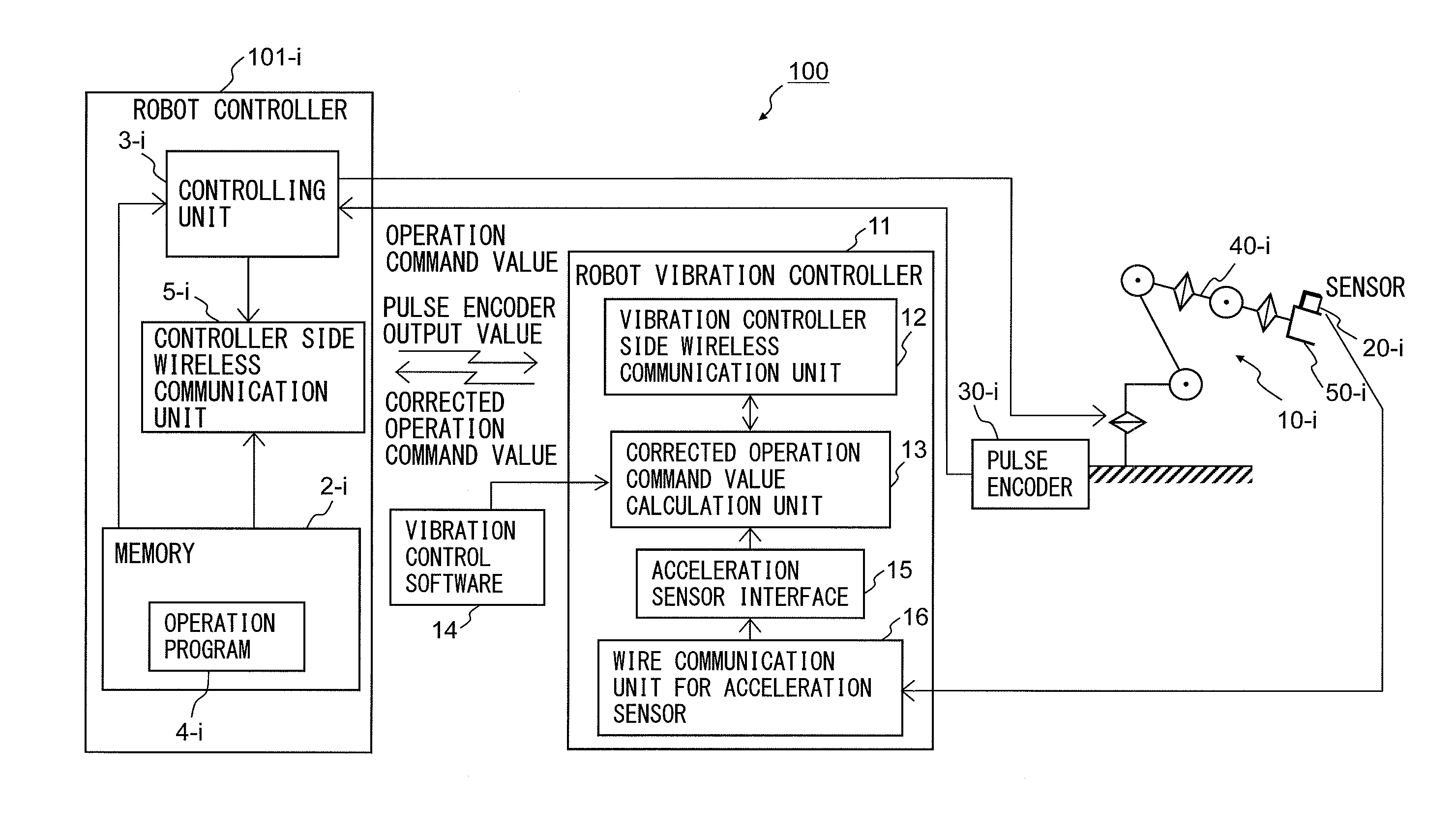
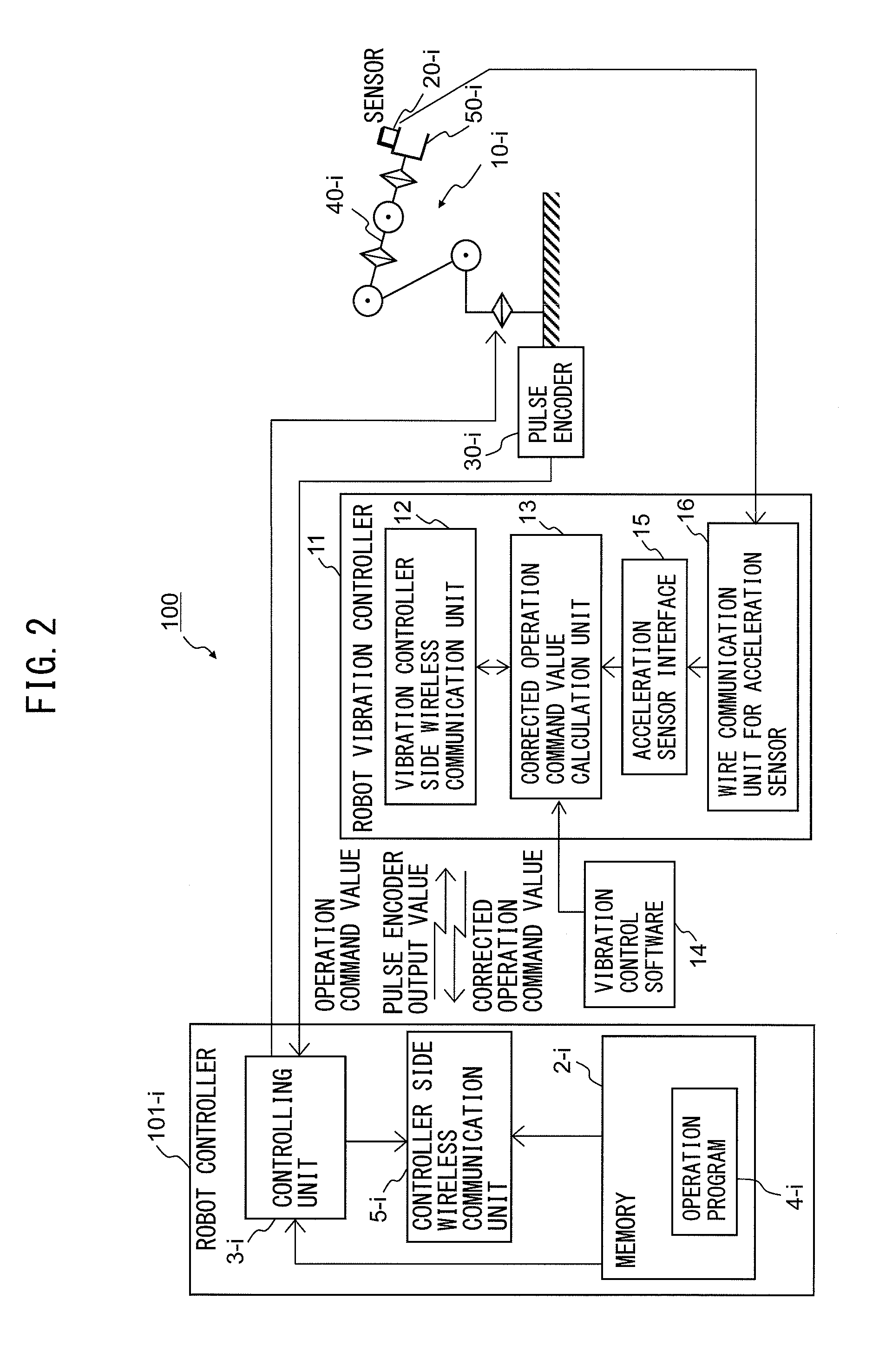
[0033]First, a vibration control robot system according to Example 1 of the present invention will be described by way of the Drawings. FIG. 2 is a block diagram of a vibration control robot system according to Example 1 of the present invention. A vibration control robot system 100 according to Example 1 includes a robot controller 101-i which controls a robot 10-i and a robot vibration controller 11, and a robot vibration controller 11 is characterized by being arranged independently of the robot controller 101-i.
[0034]As mentioned below, the one robot vibration controller 11 according to Example 1 of the present invention can perform vibration control of a plurality of (for example, n) robot controllers 101-1 to 101-n and robots 10-1 to 10-n. Therefore, the above index “i” represents any integer from 1 to n.
[0035]The robot 10-i performs a predetermined operation such as spot welding by allowing an arm 40-i to move by driving a servo motor (not illustrated) based on an operation ...
second embodiment
[0079]Next, a vibration control robot system according to Example 2 of the present invention will be described by way of the Drawings. FIG. 10 is a block diagram of the vibration control robot system according to Example 2 of the present invention. A vibration control robot system 200 according to Example 2 includes a robot controller 201-i which controls a robot 10-i and a robot vibration controller 21, and a robot vibration controller 21 is characterized by being arranged independently of the robot controller 201-i and in that communication between a controller-side wire communication unit 6-i which is a controller-side communication unit of the robot vibration controller 21 and a vibration-controller-side wire communication unit 19 which is a vibration-controller-side communication unit is performed with wires.
[0080]A difference between the vibration control robot system 200 according to Example 2 and the vibration control robot system 100 according to Example 1 is that communica...
third embodiment
[0096]Next, a vibration control robot system according to Example 3 of the present invention will be described by way of the Drawings. FIG. 14 is a block diagram of the vibration control robot system according to Example 3 of the present invention. A vibration control robot system 300 according to Example 3 includes a robot controller 301-i which controls a robot 10-i and a robot vibration controller 31, and a robot vibration controller 31 is characterized by being arranged independently of the robot controller 301-i and in that communication between the acceleration sensor 20-i of the robot 10-i and an acceleration sensor interface 15 of a robot vibration controller 31 is performed wirelessly via a wireless communication unit for acceleration sensor 22.
[0097]A difference between the vibration control robot system 300 according to Example 3 and the vibration control robot system 100 according to Example 1 is that communication between the acceleration sensor 20-i of the robot 10-i a...
PUM
 Abstract
Description
Claims
Application Information
 - R&D
- Intellectual Property
- Life Sciences
- Materials
- Tech Scout
- Unparalleled Data Quality
- Higher Quality Content
- 60% Fewer Hallucinations
Browse by: Latest US Patents, China's latest patents, Technical Efficacy Thesaurus, Application Domain, Technology Topic, Popular Technical Reports.
© 2025 PatSnap. All rights reserved.Legal|Privacy policy|Modern Slavery Act Transparency Statement|Sitemap|About US| Contact US: help@patsnap.com