Output buffer

a buffer and output technology, applied in the field of output buffers, can solve the problem of increasing the entire power consumption of the output buffer b>100/b>, and achieve the effect of reducing the additional dynamical power consumption and improving the response speed of the internal of the output buffer

Active Publication Date: 2014-01-09
NOVATEK MICROELECTRONICS CORP
View PDF2 Cites 6 Cited by
  • Summary
  • Abstract
  • Description
  • Claims
  • Application Information

AI Technical Summary

Benefits of technology

[0011]The present invention is directed to an output buffer capable of charging a compensation capacitor slowly without using a bias current of an input-stage circuit, so that a response speed of the internal of the output buffer is improved. And, without re-charging / re-discharging the compensation capacitor, additional dynamical power consumption can be reduced.

Problems solved by technology

In order to increase the large signal response speed of the output buffer 100, the bias current of the input-stage unit 110 has to be designed as larger, which results in increment of entire power consumption of the output buffer 100 and becomes a major issue in this field.

Method used


Image

  • Output buffer
  • Output buffer
  • Output buffer

Examples


Embodiment Construction

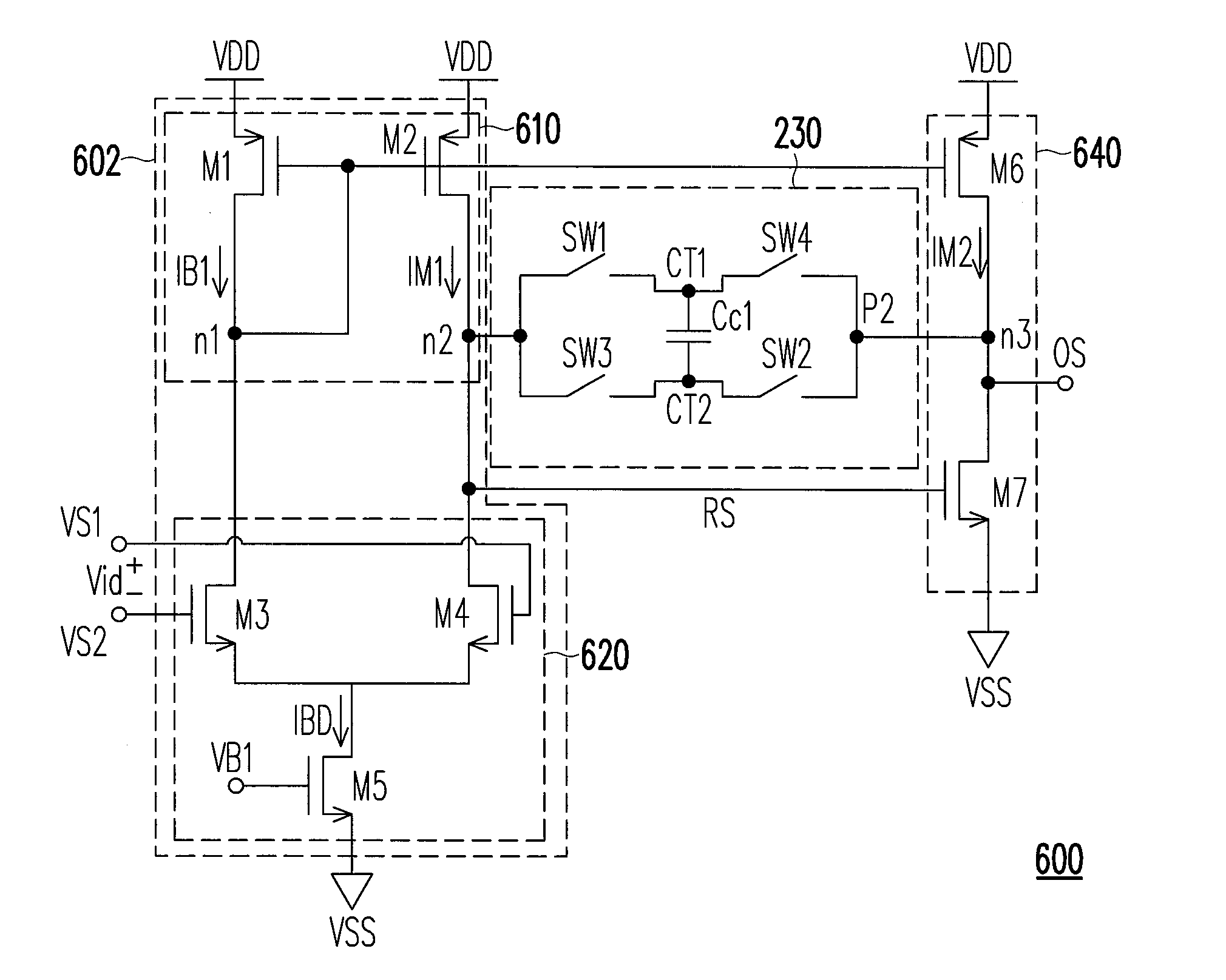
[0044]An output buffer according to embodiments of the present invention will be described hereinafter, which utilizes a technique alternatively switching a plurality of switches to change positions of two terminals coupled to a compensation capacitor, such that electrical charges on the compensation capacitor can be maintained to improve a response speed of the internal of the output buffer. Besides, without re-charging or re-discharging the compensation capacitor, additional dynamic power consumption can be reduced. In order to make the aforementioned and other objectives, features, and advantages of the present invention more comprehensible, embodiments accompanied with figures are described in detail below.

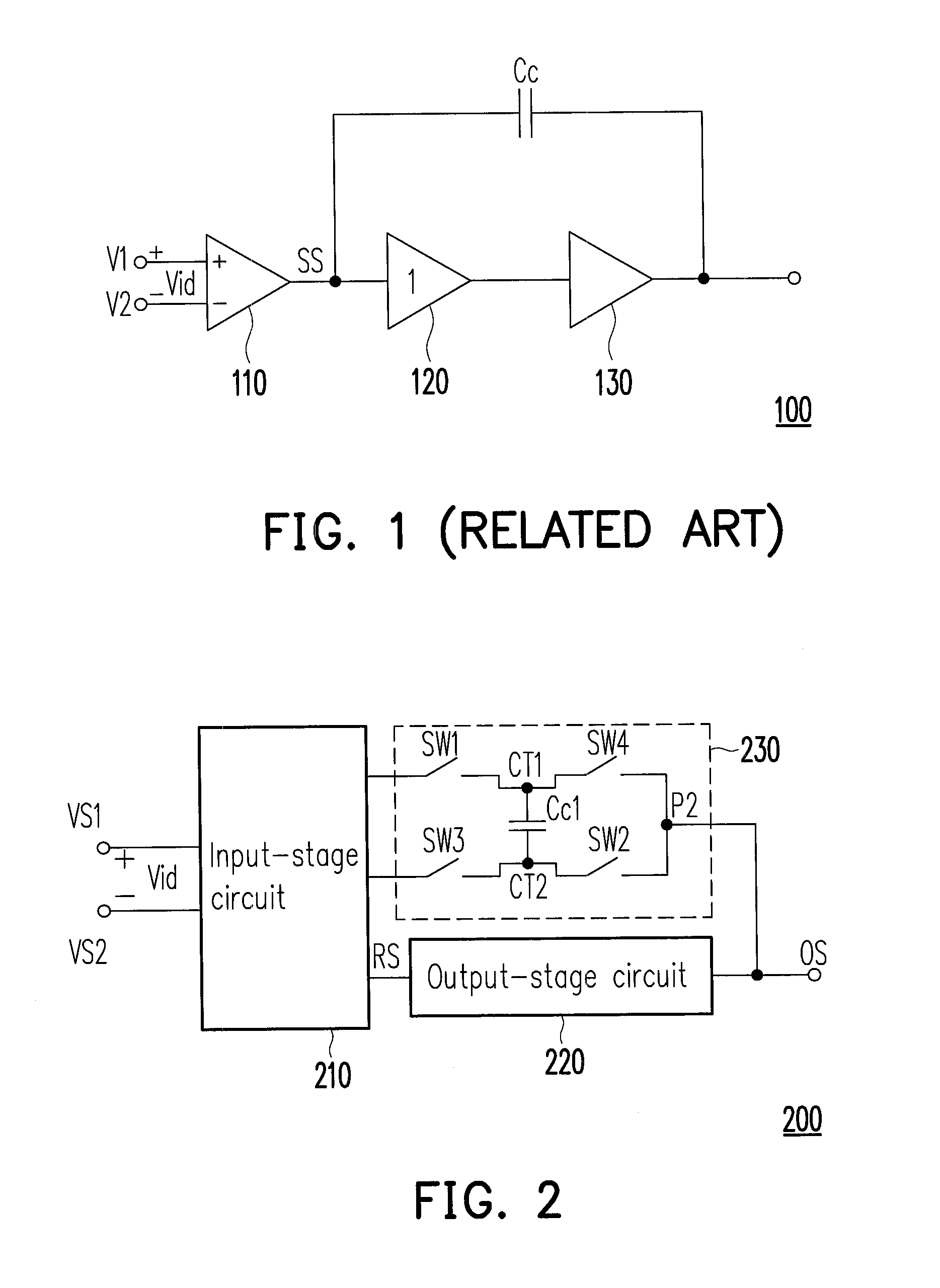
[0045]FIG. 2 is a structural schematic diagram illustrating an output buffer according to an embodiment of the present invention. Referring to FIG. 2, an output buffer 200 includes an input-stage circuit 210, an output-stage circuit 220 and a compensation circuit 230. The inpu...


PUM


Abstract

An output buffer is disclosed. The output buffer includes an input-stage circuit, an output-stage circuit and a compensation circuit. The compensation circuit includes a capacitor, a first switch, a second switch, a third switch, and a fourth switch. The input-stage circuit receives a differential input signal and outputting a response signal. The output-stage circuit receives the response signal and outputting an output signal. The first switch controls a connection between the input-stage circuit and a first terminal of the capacitor. The second switch controls the connection between an output terminal of the compensation circuit and a second terminal of the capacitor. The third switch controls the connection between the input-stage circuit and the second-terminal of the capacitor. The forth switch controls the connection between the output terminal of the compensation circuit and the first terminal of the capacitor.

Description

CROSS-REFERENCE TO RELATED APPLICATION[0001]This application claims the priority benefit of Taiwan application serial no. 101124261, filed on Jul. 5, 2012. The entirety of the above-mentioned patent application is hereby incorporated by reference herein and made a part of this specification.BACKGROUND[0002]1. Field of the Invention[0003]The present invention is directed to an output buffer having a compensation capacitor and more particularly, to an output buffer having switches for switching two terminals of a compensation capacitor.[0004]2. Description of Related Art[0005]An output buffer mainly functions as providing a buffering mechanism for impedance matching to a signal terminal and a load terminal. As for the signal terminal, an input terminal of the output buffer provides an input of a quite high input impedance to completely receive a signal outputted from the signal terminal so as to avoid an actuation of the signal inputted from the output buffer. In addition, an output t...

Claims


Application Information

Patent Timeline
Patent Type & Authority Applications(United States)
IPC IPC(8): H03K3/012
CPCH03K3/012H03K19/00H03F3/3023H03F3/45183H03F3/45219H03F2203/45634H03F2203/45674
Inventor CHEN, CHUN-HUNG
Owner NOVATEK MICROELECTRONICS CORP
Why Eureka
Try Eureka