Projection-type video display apparatus

a video display and projection-type technology, applied in the field of projection-type video display apparatuses, can solve the problems of increasing manufacturing costs, generating difficulty and/or inconvenience, and difficulty in obtaining video light, and achieve the effect of increasing the manufacturing cost of the apparatus and enlarging the size of the display screen

Active Publication Date: 2014-01-09
MAXELL HLDG LTD
View PDF3 Cites 2 Cited by
  • Summary
  • Abstract
  • Description
  • Claims
  • Application Information

AI Technical Summary

Benefits of technology

[0013]The present invention is accomplished by taking such problems in the conventional technologies mentioned above into the consideration thereof, and an object thereof is to provide a projection-type video display apparatus, having housing structures for dissolving such problems in the conventional technologies mentioned above, i.e., having no difficulty and / or inconvenience in the transportation / conveyance of the apparatus, even if enlarging the size of the display screen, and not bringing about the increase of the manufacturing costs of the apparatus.

Problems solved by technology

For example, with the video display apparatus disclosed in the Patent Document 1 mentioned above, the housing also becomes large accompanying with large-sizing of the display screen thereof, and for that reason, there is generated difficulty and / or inconvenience, in particular, in transportation / conveyance of that apparatus.
Moreover, since a desired accuracy for manufacturing is requested in the manufacturing thereof, there is a problem that it results into an increase of manufacturing costs.
However, with the video display apparatus disclosed in the Patent Document 1 mentioned above, such the problem can be dissolved; however, if applying it into the projection-type video display apparatus equipped with the present or existing video projection unit, not applying the hologram therein, it is difficult to obtain the video light, being high in the contrast and bright.

Method used


Image

  • Projection-type video display apparatus
  • Projection-type video display apparatus
  • Projection-type video display apparatus

Examples


Embodiment Construction

[0030]Hereinafter, detailed explanation will be made about embodiments, according to the present invention, by referring to the drawings attached herewith. However, in each of the drawings given below, an element(s) having the common function(s) thereof will be shown by attaching the same reference numeral(s), and an explanation of that explained once will omitted, herein, thereafter, for avoiding duplication thereof.

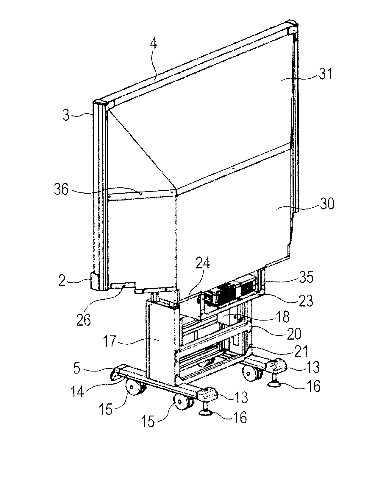
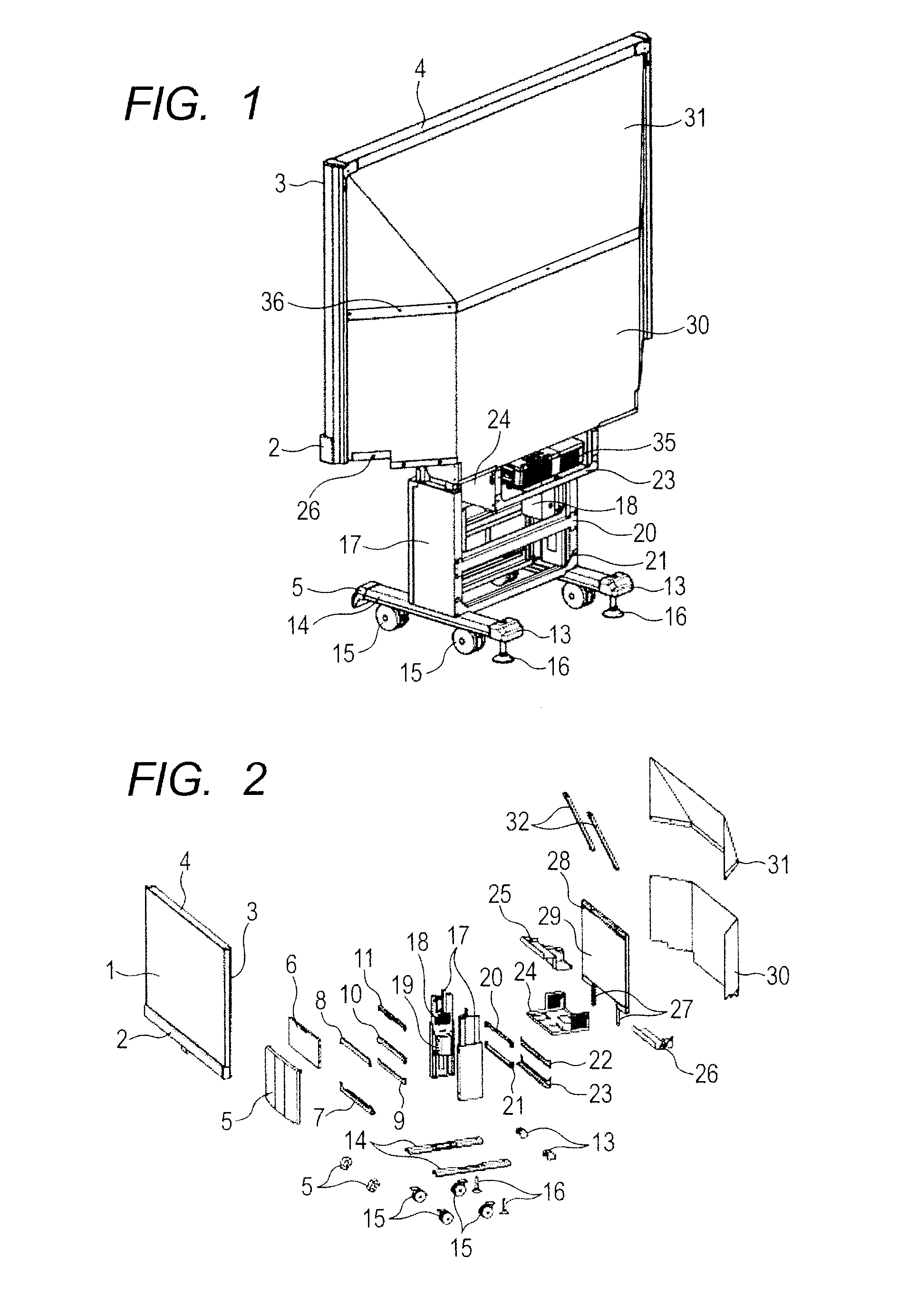
[0031]First of all, FIG. 1 attached herewith shows a projection-type video display apparatus, according to an embodiment of the present invention, in the form of a perspective view of the entire thereof when being seen from the rear, and in this figure, a reference numeral 2 depicts a frame body, being attached on a lower end of a screen of a projection type, which builds up a projection surface in that projection-type video display apparatus, a reference numeral 3 frame bodies, being attached on both ends thereof, and a reference numeral 4, being attached on the upper ...


PUM


Abstract

Projection-type video display apparatus, for base of transportation/conveyance if a display screen thereof is large-sized, and reducing energy necessary for the transportation and/or carbon dioxide discharging, thereby being friendly to the global environment.
In the projection-type video display apparatus, for enlargedly projecting an image light, which is projected from a video projection unit 35, for projecting an image displayed on a video display screen as the image light, on a rear surface of a transmission-type screen, the video projection unit builds up an oblique projection optic system, and further a transmission-type screen 1 and a plane mirror 29 are disposed on a cabinet portion “C” including a side plate 17, being perpendicularly fixed, independently, in parallel with each other, and on the rear surface of the transmission-type screen are attached foldable back covers 30 and 31, detachably, so as to cover a rear surface of the plane mirror.

Description

TECHNICAL FIELD[0001]This application relates to a projection-type video display apparatus.BACKGROUND OF THE INVENTION[0002]As a large-scaled (or large-sized) video display apparatus for enlarging a display screen is already known and is widely utilized a projection-type video display apparatus, which projects a video upon a transmission-type projection surface, through a video projection unit for projecting, with using a video display element, such as, a liquid crystal panel, etc.[0003]Conventionally, for example, in the following Patent Document 1 is already disclosed the structures, in which a mirror, for reflecting the video from the video projection unit thereon, is attached at a predetermined inclination angle, on an inner wall of a rear surface of a housing, standing a projection screen on a front surface, while storing the video projection unit in an inside thereof.[0004]Also, in the following Patent Document 2 is already known a projection display apparatus, which does not ...

Claims


Application Information

Patent Timeline
Patent Type & Authority Applications(United States)
IPC IPC(8): H04N9/31
CPCH04N9/3173G03B21/28G02B3/08G02B27/283G03B21/10G03B21/30G03B21/62H04N1/00559H04N1/00562H04N1/1065
Inventor HIRATA, KOJIMATSUZAWA, TOSHIHIKOSATO, TADASHI
Owner MAXELL HLDG LTD
Why Eureka
Try Eureka