

Optical fan-in/fan-out device
a technology of optical fan and fan body, which is applied in the direction of optical fiber with multi-layer core/cladding, optical waveguide light guide, instruments, etc., can solve the problem of easy excessive loss, achieve the effect of reducing loss, reducing loss, and reducing loss
- Summary
- Abstract
- Description
- Claims
- Application Information
AI Technical Summary
Benefits of technology
Problems solved by technology
Method used
Image

Examples
first embodiment
[0035]A preferred first embodiment of the present invention will be described in detail with reference to the drawings.
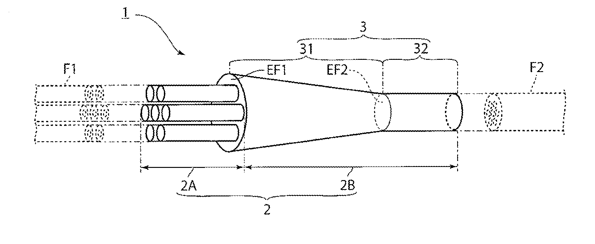
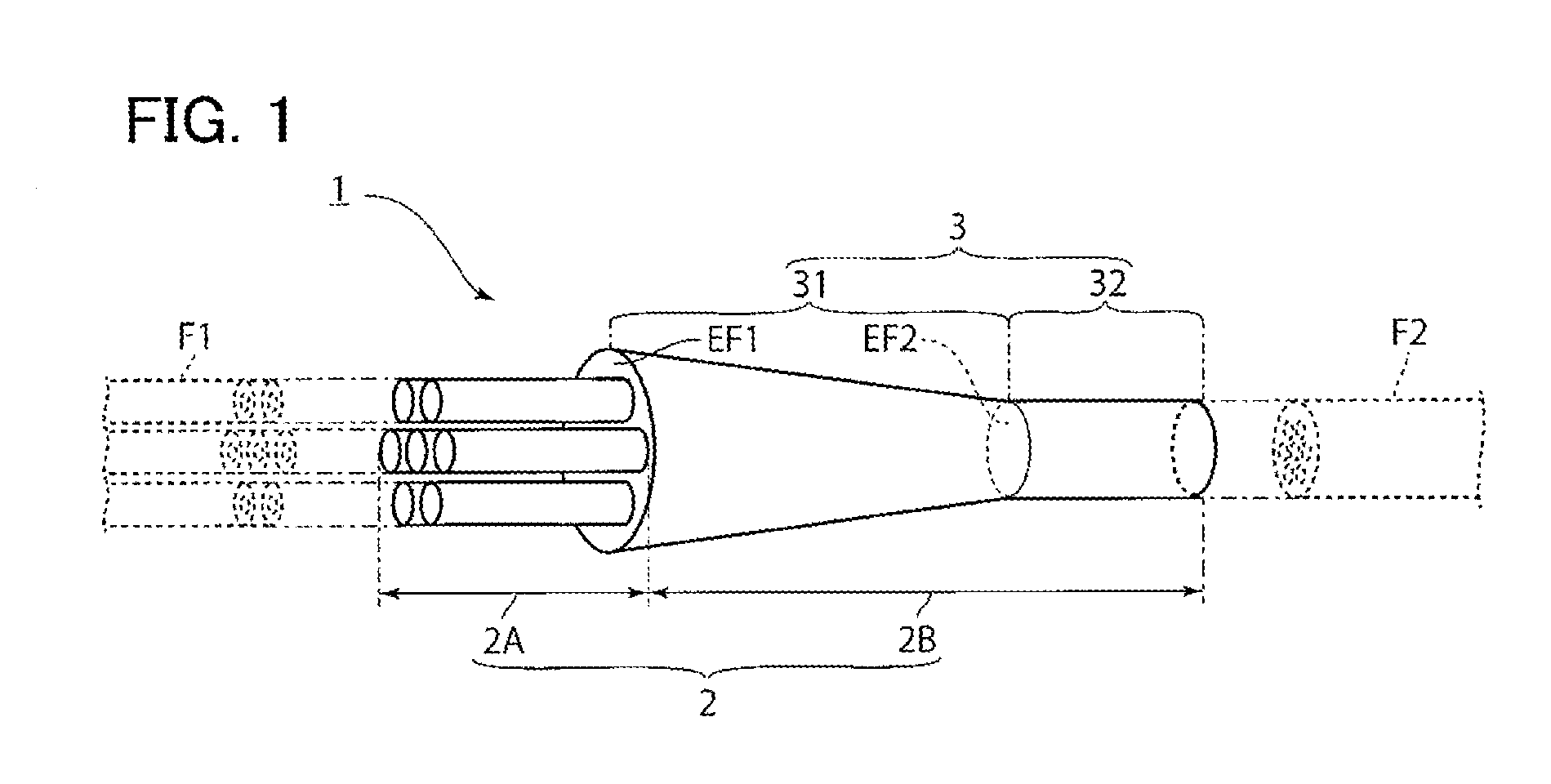
[0036]FIG. 1 is a diagram illustrating an optical fan-in / fan-out device 1 according to a first embodiment. As illustrated in FIG. 1, the optical fan-in / fan-out device 1 according to the embodiment includes a plurality of relay fibers 2 and an outer circumference clad 3.
[0037]Each relay fiber 2 is an optical fiber for relaying a core of a single-core optical fiber F1 and one core of a multi-core fiber F2 and has an exposed portion 2A exposed from the outer circumference clad 3.
[0038]In the exposed portion 2A, the relay fibers 2 are separated from each other by an air gap, and an end surface of the relay fiber 2 is considered to be a portion which is to be fused and connected to the one end surface of the single-core optical fiber F1.
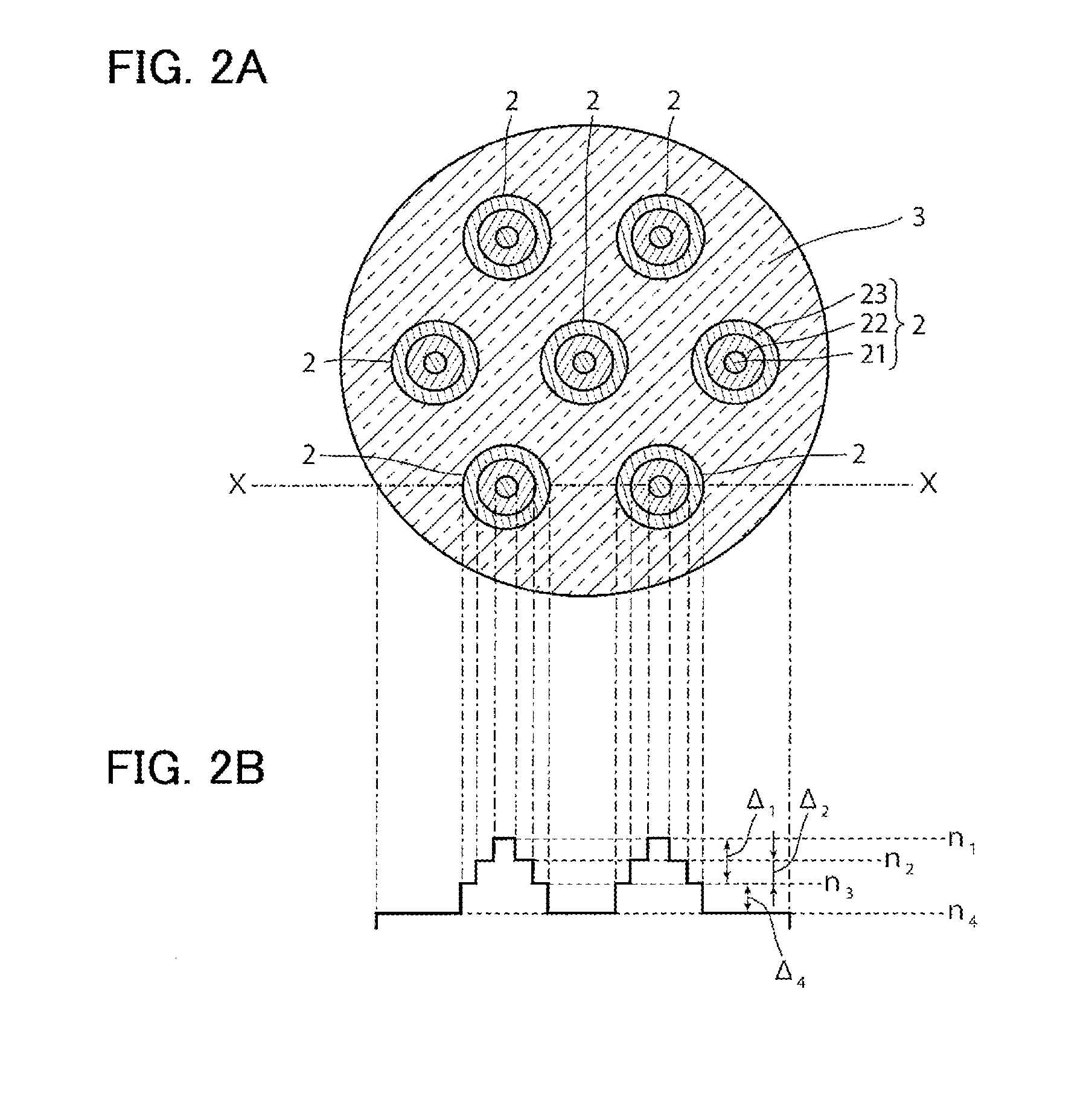
[0039]FIGS. 2A and 2B are diagrams illustrating a state of a cross section perpendicular to a longitudinal direction of the optical fan-...
second embodiment
[0081]Next, a preferred second embodiment of the present invention will be described in detail with reference to the drawings. In addition, the components which are the same as or equivalent to the components of the first embodiment are denoted by the same reference numerals, and the description thereof is not presented except for particularly described cases.
[0082]FIGS. 5A and 5B are diagrams illustrating a state of an optical fan-in / fan-out device according to a second embodiment as seen in the same point of view as FIGS. 2A and 2B. As illustrated in FIG. 5A, the optical fan-in / fan-out device according to the second embodiment is different from the optical fan-in / fan-out device I according to the first embodiment in that the optical fan-in / fan-out device according to the embodiment includes a new outermost circumference clad 4 which surrounds the circumference surface of the outer circumference clad 3 without clearance.
[0083]As illustrated in FIG. 5B, the refractive index n5 of th...
example
[0091]In the optical fan-in / fan-out device 1, in the case where a length of the tapered portion 31 was fixed to 5 mm, the radius r1S and relative refractive index difference Δ1 of the first core 21 and the relative refractive index difference Δ2 of the second core were fixed to predetermined values, and the radius r2S of the second core and the elongation rate of the relay fiber 2 were changed, numerical experiments with respect to the effective cross-sectional area of the core (effective core cross-sectional area) of the relay fiber portion 2B were performed. In addition, in the numerical experiments, a wavelength of light incident on the relay fiber portion 23 was set to 1550 nm.
[0092]FIGS. 7A to 7D are graphs illustrating a change in effective cross-sectional area of cores in the case where the elongation rate of the relay fiber 2 is set to 1 / 3.4. FIGS. 8A to 8D are graphs illustrating a change in effective cross-sectional area of cores in the case where the elongation rate of th...
PUM
 Abstract
Description
Claims
Application Information