Transmission with disengageable variator

a technology of disengageable variators and transmission lines, applied in the field of transmission, can solve the problems of large gear spread, large gear spread, and large design complexity, and achieve the effects of compact structure, low structure complexity, and low cos

Inactive Publication Date: 2014-01-09
ZF FRIEDRICHSHAFEN AG
View PDF7 Cites 7 Cited by
  • Summary
  • Abstract
  • Description
  • Claims
  • Application Information

AI Technical Summary

Benefits of technology

[0008]The purpose of the present invention is to provide a transmission which can be made compact and

Problems solved by technology

Since in addition the step intervals between the gears should not exceed a certain size, the result is a large number of gears and correspondingly greater design complexity.
As already mentioned at the beginning, however, starting gears are also needed so that a large gear spread results.
Such an increase, howe

Method used


Image

  • Transmission with disengageable variator
  • Transmission with disengageable variator
  • Transmission with disengageable variator

Examples


Embodiment Construction

[0028]In the two figures the same or corresponding components are given the same indexes.

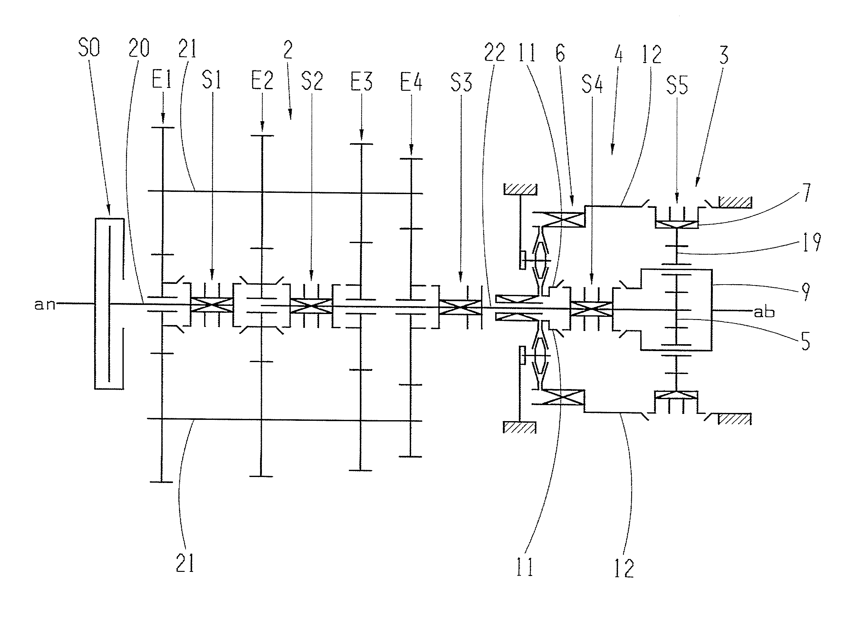
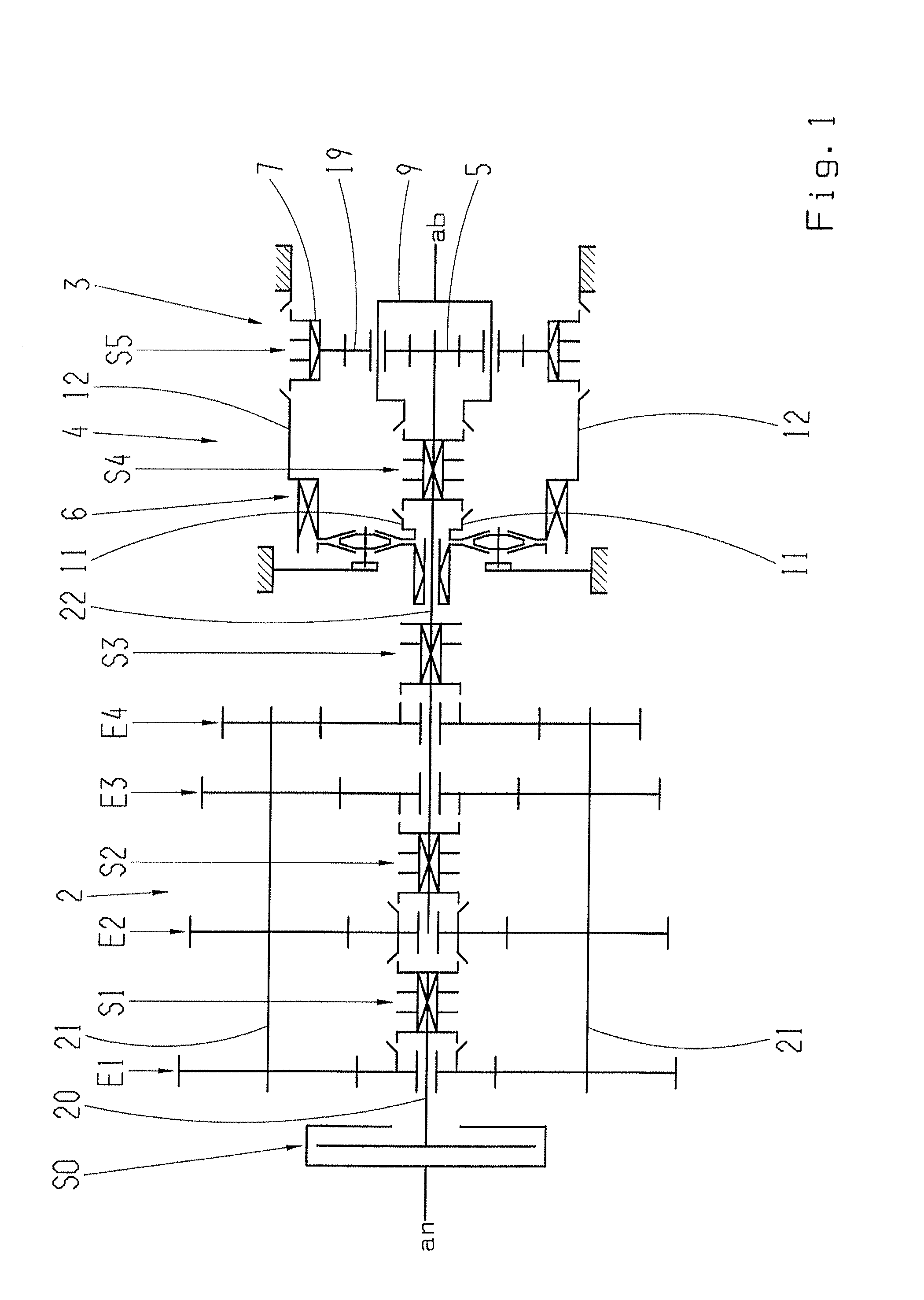
[0029]FIG. 1 shows a gear layout of a first gearset representing a first example embodiment according to the invention. The transmission 1 shown comprises a main transmission in the form of a countershaft transmission 2 and a range group 4 connected downstream therefrom, which comprises an epicyclic transmission or planetary gear system. The countershaft transmission 2 and the range group 4 can be regarded as transmission groups of the group transmission. Upstream from the countershaft transmission 2 is connected a clutch S0. The drive input (an) to the clutch can for example be provided by a motor, in particular an internal combustion engine. The countershaft transmission 2 is driven by a central input shaft 20 and comprises four shifting planes E1, E2, E3, E4 and two countershafts 21. As shown, on the countershafts 21 are preferably arranged respective fixed wheels (gearwheels) which mesh with...


PUM


Abstract

A transmission, preferably for driving a motor vehicle, includes a multi-gear main transmission and a range group, that is connected downstream from the main transmission and comprises an input shaft and an epicyclic gear system. The epicyclic gear system comprises elements in the form at least of a central gearwheel and a planetary carrier. Furthermore, the transmission comprises a first connection for driving one of the elements of the epicyclic gear system by way of the input shaft of the range group and a variator, as well as a second connection that can be engaged with the first connection for driving a further element of the elements of the epicyclic gear system. When the second connection is engaged, the input shaft of the range group drives the variator and a drive output of the variator drives the further element of the epicyclic gear system.

Description

[0001]This application claims priority from German patent application serial no. 10 2012 211 531.5 filed Jul. 3, 2012.FIELD OF THE INVENTION[0002]The invention concerns a transmission, in particular for motor vehicles.BACKGROUND OF THE INVENTION[0003]Particularly for commercial vehicles such as trucks, transmissions with a wide gear spread and a large starting gear ratio are needed. On the one hand a main driving gear is usually needed, which with the aim of optimizing fuel consumption enables a maximum permissible top speed with a low engine speed. In many cases such a driving gear is made as a direct gear in order to ensure the greatest possible efficiency. On the other hand forward-starting gears and also in particular reverse-starting gears are needed, which enable maneuvering at low speed and starting with low clutch wear. Since in addition the step intervals between the gears should not exceed a certain size, the result is a large number of gears and correspondingly greater de...

Claims


Application Information

Patent Timeline
IPC IPC(8): F16H37/02
CPCF16H37/022F16H37/084F16H2037/0893F16H37/046
Inventor REISCH, MATTHIASHUNOLD, BERNARD
Owner ZF FRIEDRICHSHAFEN AG
Why Eureka
Try Eureka