Prosthetic foot with hybrid layup

a technology of prosthetic feet and hybrid materials, applied in the field of prosthetic feet, can solve the problems of increasing the weight of the foot, increasing the rigidity and thickness of the prosthetic foot, and corresponding increases in stiffness and stiffness, so as to achieve the effect of increasing strength, increasing flexibility or stiffness, and increasing strength

Inactive Publication Date: 2014-01-09
OSSUR HF
View PDF10 Cites 0 Cited by
  • Summary
  • Abstract
  • Description
  • Claims
  • Application Information

AI Technical Summary

Benefits of technology

[0006]In view of the foregoing, there is a need for an improved prosthetic foot that can provide the same flexibility or stiffness as a similarly sized conventional prosthetic foot, while providing an increase in strength over the similarly sized conventional prosthetic foot. Additionally, there is a need for an improved prosthetic foot that can provide the same strength as a similarly sized conventional prosthetic foot, while providing an increase in flexibility over the similarly sized conventional prosthetic foot. Such improved prosthetic feet would be able to provide the enhanced strength or flexibility with a limited and / or minimal increase in overall thickness and / or weight as compared to the similarly sized conventional prosthetic feet.

Problems solved by technology

In a conventional prosthetic foot, designing the prosthetic foot for an increase in strength requires an increase in the overall thickness of the prosthetic foot and results in a corresponding increase in stiffness (i.e., a decrease in flexibility or flexion of the prosthetic foot).
The increase in stiffness and thickness adds to the weight of the foot and may require a user to exert more force on the foot during ambulation.

Method used


Image

  • Prosthetic foot with hybrid layup
  • Prosthetic foot with hybrid layup
  • Prosthetic foot with hybrid layup

Examples


Embodiment Construction

[0020]Embodiments of the invention will now be described with reference to the accompanying figures, wherein like numerals refer to like elements throughout. Although several embodiments, examples and illustrations are disclosed below, it will be understood by those of ordinary skill in the art that the invention described herein extends beyond the specifically disclosed embodiments, examples and illustrations and can include other uses of the invention and obvious modifications and equivalents thereof. The terminology used in the description presented herein is not intended to be interpreted in any limited or restrictive manner simply because it is being used in conjunction with a detailed description of certain specific embodiments of the invention. In addition, embodiments of the invention can comprise several novel features and no single feature is solely responsible for its desirable attributes or is essential to practicing the inventions herein described.

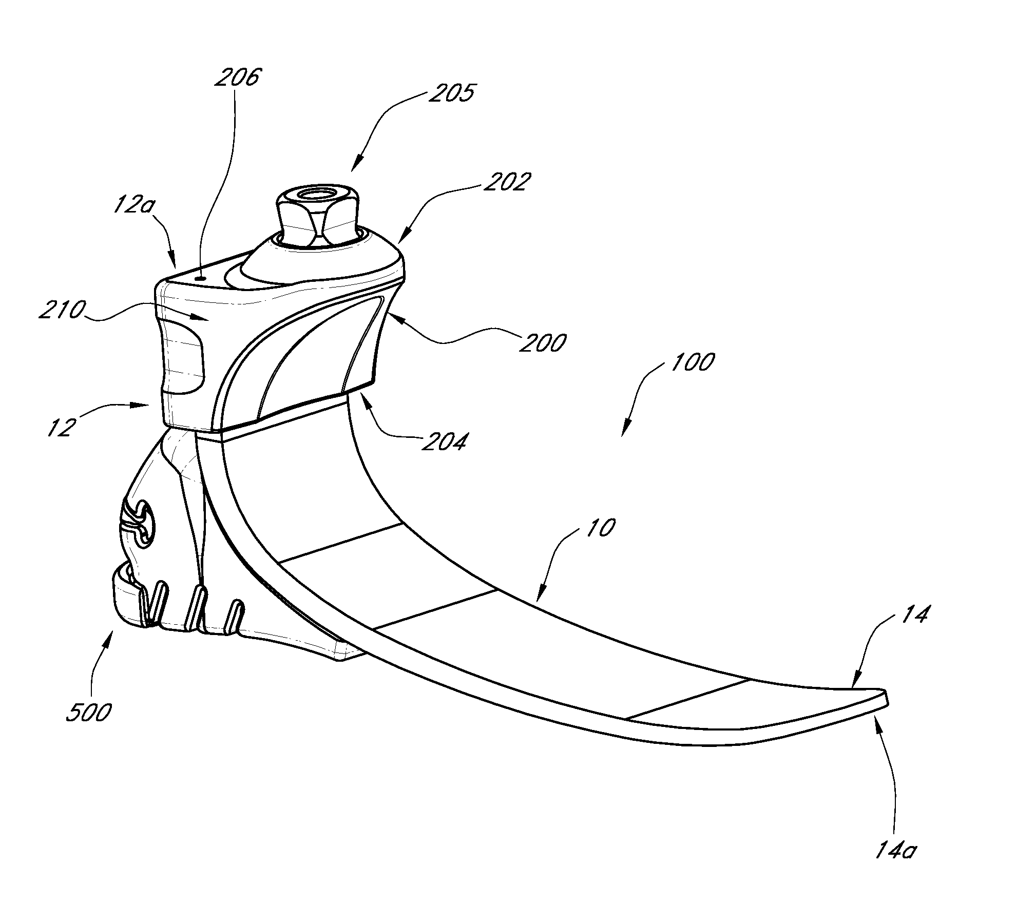
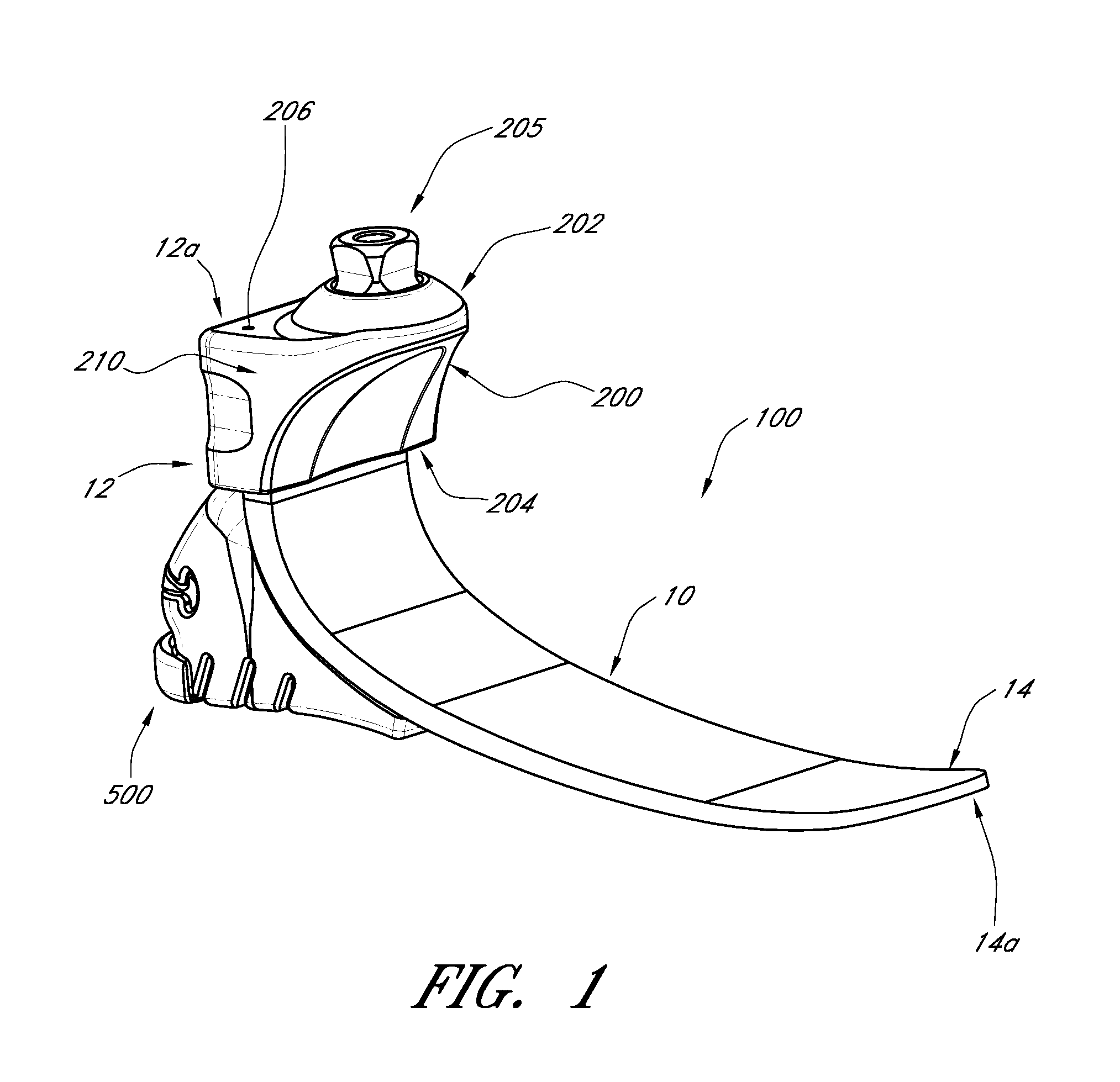
[0021]FIG. 1 illustrat...


PUM


Abstract

A prosthetic foot has a plate-like foot member with a core section substantially defined by one or more layers comprising a first material fiber, an upper section disposed above the core section, the upper section substantially defined by one or more layers comprising a second material fiber, and a lower section disposed below the core section, the lower section substantially defined by one or more layers comprising a third material fiber, where the upper, lower and core sections together define a total thickness of the plate-like elongate foot member. An idealized ratio of the cross sectional area of each section can be determined such that under an applied load provided to the hybrid layup, the ratio of maximum stress of a given section over the flexural strength of that given section is approximately equal for all sections of the hybrid layup. The hybrid layup arrangement can be configured to have a greater strength, but generally the same stiffness, as a similar foot member made of carbon fiber.

Description

CROSS-REFERENCE TO RELATED APPLICATIONS[0001]This application claims the benefit of priority under 35 U.S.C. §119(e) of U.S. Provisional Application No. 61 / 668,885 filed on Jul. 6, 2012, the entirety of which is incorporated herein by reference.BACKGROUND OF THE INVENTION[0002]1. Field of the Invention[0003]The present application is directed to prosthetic feet, and more particularly to prosthetic feet having a hybrid material layup arrangement.[0004]2. Description of the Related Art[0005]Various types of prosthetic foot devices are available as substitutes for human feet. Conventional prosthetic feet, which can be made of various layers of carbon fiber, are generally provided in a number of sizes and categories (e.g., activity categories) to fit the different population of users and activity levels of the users. For example, users who engage in low impact activities such as walking and gardening may need a prosthetic foot with a particular stiffness and / or strength. Users who engag...

Claims


Application Information

Patent Timeline
Patent Type & Authority Applications(United States)
IPC IPC(8): A61F2/66
CPCA61F2/66A61F2/5044A61F2002/503A61F2002/5055A61F2002/5056A61F2002/6657
Inventor GUNNARSSONN, RAGNAR ORNLECOMTE, CHRISTOPHE G.SKULASON, BENEDIKT
Owner OSSUR HF
Why Eureka
Try Eureka