Pneumatic tire and method for producing same

a pneumatic tire and pneumatic technology, applied in the field of pneumatic tires and a production method, can solve the problems of large amount of time, inability to effectively produce a noise damper, and the tire production process as a whole cannot be considered very labor-intensive, so as to reduce cavity resonance, improve productivity, and improve the productivity of pneumatic tires.

Inactive Publication Date: 2014-01-16
MICHELIN & CO CIE GEN DES ESTAB MICHELIN +1
View PDF3 Cites 14 Cited by
  • Summary
  • Abstract
  • Description
  • Claims
  • Application Information

AI Technical Summary

Benefits of technology

[0012]The present invention has therefore been devised in order to solve the abovementioned problems in the prior art, and the aim of the invention lies in providing a pneumatic tire which has better productivity and is provided with a noise damper in the tire cavity, and a method for producing same.
[0028]The pneumatic tire and method for producing same according to the present invention make it possible to improve productivity while reducing cavity resonance.

Problems solved by technology

However, with the technology described in Patent Document 1, the preparation steps require a large amount of time, such as preparing the sponge material which is pre-molded into a strip shape, cutting this material to the length to be attached, attaching the double-sided adhesive tape or the like to the attachment surface, and buffing the internal surface of the tire, etc., and there is a problem in that the tire production process as a whole can in no way be considered very labor efficient.
Furthermore, there is a problem with the technology described in Patent Document 1 and Patent Document 2 in that it is not possible to effectively produce a noise damper that can respond to the recent requirement of further reducing disagreeable low-frequency sound waves which are transmitted to vehicle passengers.

Method used


Image

  • Pneumatic tire and method for producing same
  • Pneumatic tire and method for producing same
  • Pneumatic tire and method for producing same

Examples


Embodiment Construction

[0033]A preferred mode of embodiment of the present invention will be described below with reference to the figures.

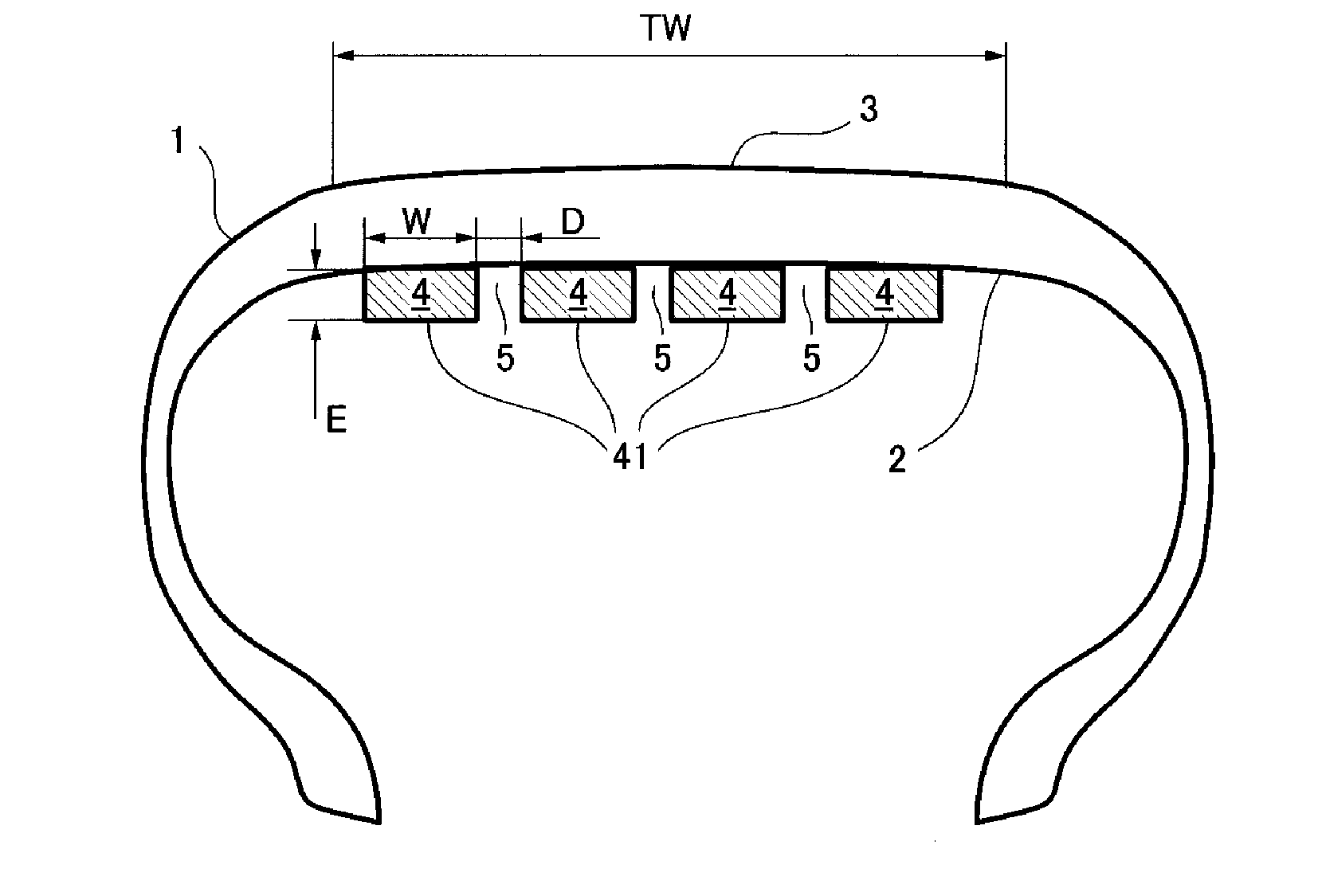
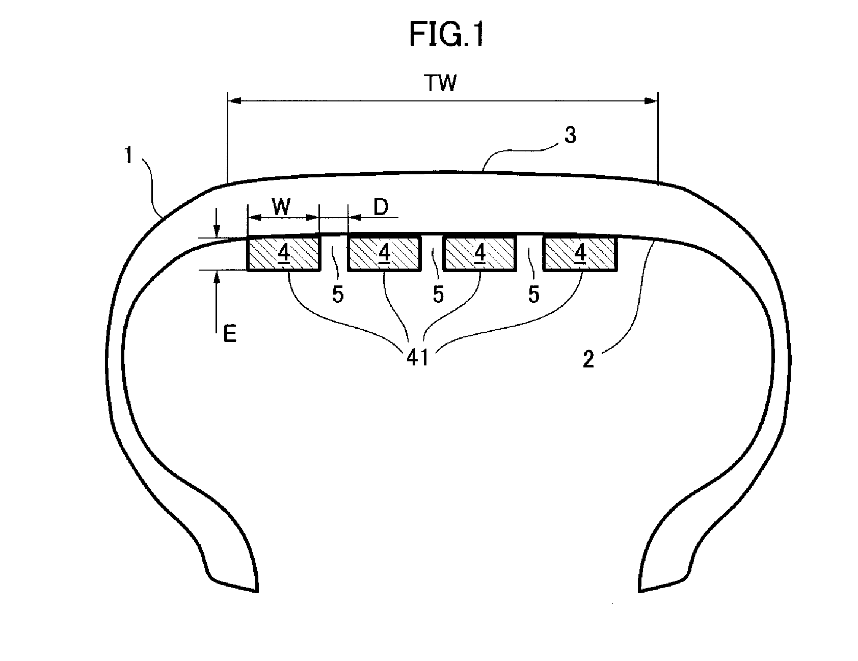
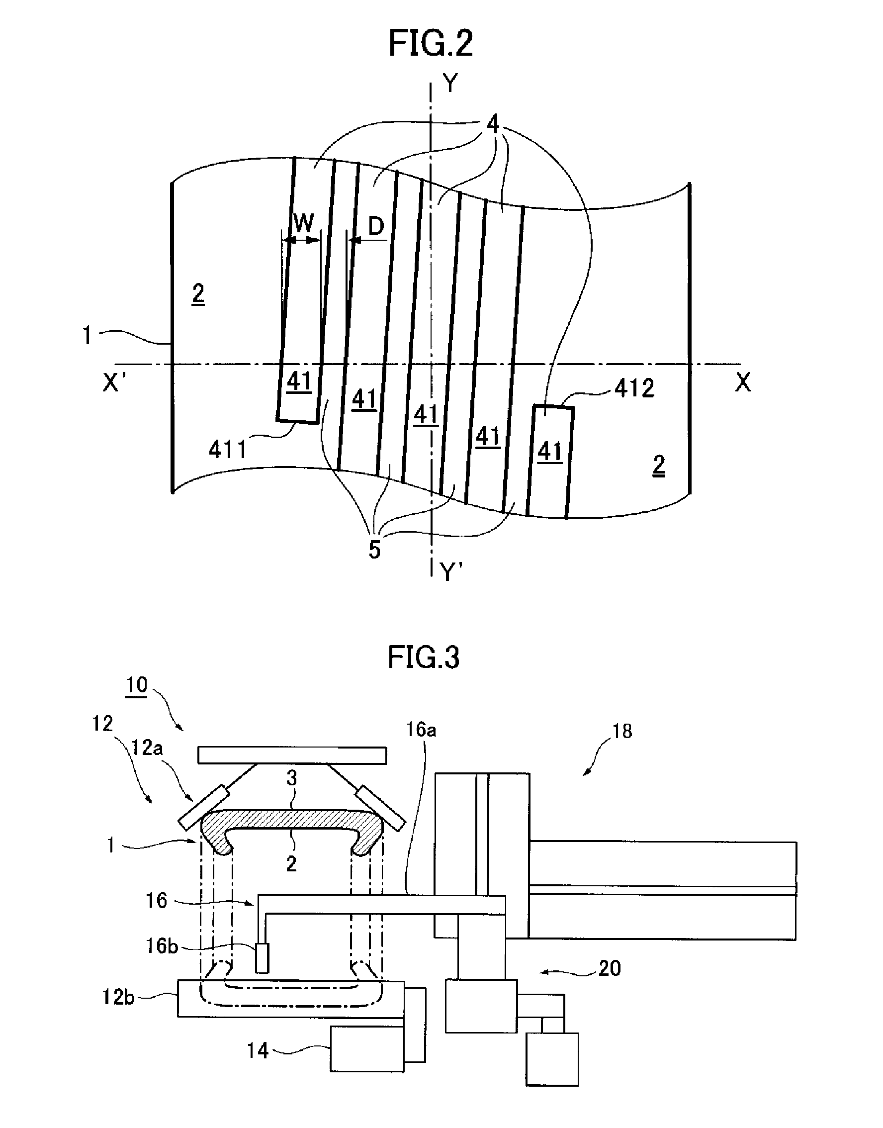
[0034]The pneumatic tire produced by means of the production method according to a mode of embodiment of the present invention will be described first of all with the aid of FIGS. 1 and 2. The method for producing a pneumatic tire according to a mode of embodiment of the present invention will be described later with the aid of FIGS. 3 and 4.

[0035]FIG. 1 schematically shows the cross section in the radial direction of a pneumatic tire provided with a noise damper, produced by means of the production method according to a mode of embodiment of the present invention, and FIG. 2 schematically shows the tire internal surface of a pneumatic tire provided with a noise damper, produced by means of the production method according to a mode of embodiment of the present invention. In FIG. 2 the circumferential direction of the tire is denoted by YY′, and the axial direction of t...


PUM


Abstract

A method for producing a pneumatic tire in which a noise damper in the form of at least one continuous ribbon for reducing cavity resonance in a tire cavity is provided on the internal surface of a tire on the inside in the radial direction of the tire corresponding to the tire tread, including, providing a vulcanized and shaped tire; mixing a composition for forming the noise damper with a foaming agent to produce a liquid composition; rotating the tire in an upright state by means of a tire holding and rotation device, and introducing the liquid composition onto the tire internal surface by a device for introducing the liquid composition; varying the relative positional relationship of the pneumatic tire and the introduction implement in the axial direction of the tire while introducing the liquid composition is introduced onto the tire internal surface, and forming the liquid composition into a gel; and foaming and drying the gelled liquid composition.

Description

BACKGROUND[0001]1. Technical Field[0002]The present invention relates to a pneumatic tire and to a method for producing same, and specifically the present invention relates to a pneumatic tire which is provided with a noise damper in the form of a continuous ribbon for suppressing cavity resonance generated in a tire cavity, and to a method for producing same.[0003]2. Description of Related Art[0004]Resonant vibration (cavity resonance) in a tire cavity is generated by the vibration of air enclosed in the tire cavity. The air in the tire cavity is generally excited by deformation of the tire tread part and sidewall part as the tire travels, and air enclosed in the annular cavity acts as an air column when this air is excited.[0005]Sound waves which are excited in the tire cavity are transmitted inside the vehicle compartment as a solid-borne sound which spreads through the wheels, suspension and motor vehicle body, and is felt by vehicle passengers as disagreeable low-frequency nois...

Claims


Application Information

Patent Timeline
Patent Type & Authority Applications(United States)
IPC IPC(8): B60C5/00
CPCB60C19/002B29D30/0061Y10T152/10495
Inventor PARFONDRY, ALAINDELFINO, ANTONIOGREVERIE, LUDOVIOFOMBELLE, DAMLEN
Owner MICHELIN & CO CIE GEN DES ESTAB MICHELIN
Why Eureka
Try Eureka