Seatbelt retractor

a retractor and seatbelt technology, applied in the field of seatbelt retractors, can solve the problems of increasing the compressive force required for inserting the force-transmitting element, affecting the responsive behavior of the force-limiting device, etc., and achieves the effect of sufficient tightness and sufficient pressure build-up

Active Publication Date: 2014-01-16
TRW AUTOMOTIVE GMBH
View PDF10 Cites 53 Cited by
  • Summary
  • Abstract
  • Description
  • Claims
  • Application Information

AI Technical Summary

Benefits of technology

[0021]Preferably the rear end of the force-transmitting element is conically widened. In the case of a pyrotechnic drive unit a sealing of the force-transmitting element against the tubular portion or toward the drive unit is required to prevent the gas from flowing past the force-transmitting element so that sufficient pressure build-up is possible. For this purpose, usually behind the force-transmitting element a ball or any other suitable sealing member is provided. In accordance with the invention, this sealing member is replaced by a conical widening of the force-transmitting element so that no additional component part is required for sealing. The widening is formed so that the force-transmitting element peripherally contacts the inner wall of the tubular portion and thus completely seals the tubular portion. In the case of an increase in pressure in the tubular portion the seal is automatically forced against the tubular wall by the conical widening so that sufficient tightness is ensured even in the case of increasing pressure.

Problems solved by technology

To this end, an additional deformation has to take place which results in an increase in the compressive force required for inserting the force-transmitting element.
However, this affects the responsive behavior of the force-limiting device, as in the case of force limitation this compressive force has to be overcome in addition to the resistance of the force limiter.

Method used


Image

  • Seatbelt retractor
  • Seatbelt retractor
  • Seatbelt retractor

Examples


Embodiment Construction

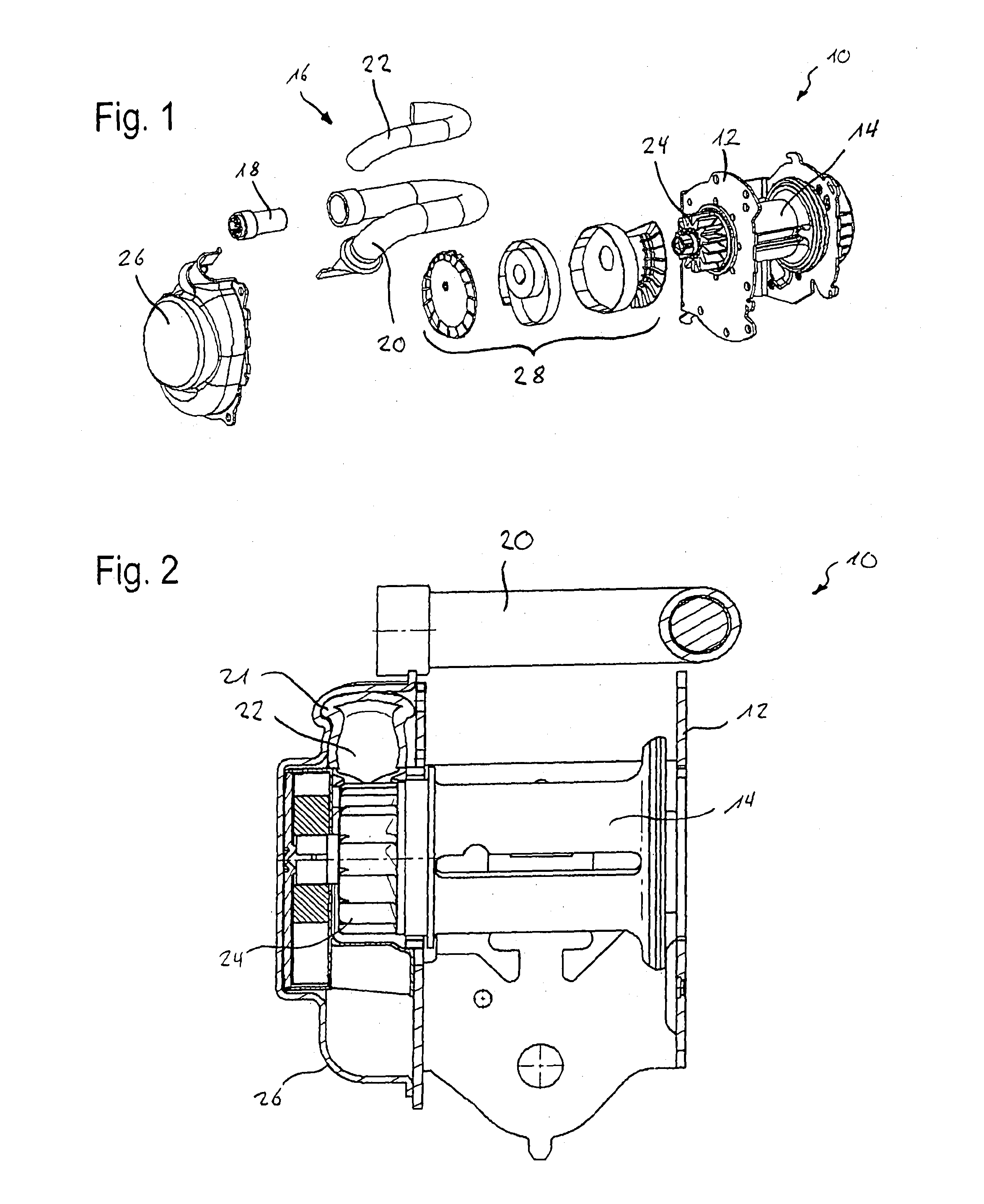
[0027]In FIG. 1 the substantial component parts of a belt retractor 10 comprising a pyrotechnically driven belt tensioner 16 are shown. In FIG. 2 the belt retractor is illustrated in the assembled state. The belt retractor 10 comprises a frame 12 to which a belt reel 14 is pivoted onto which a seat belt can be wound. Furthermore the belt retractor 10 includes a force-limiting device not shown here in detail.

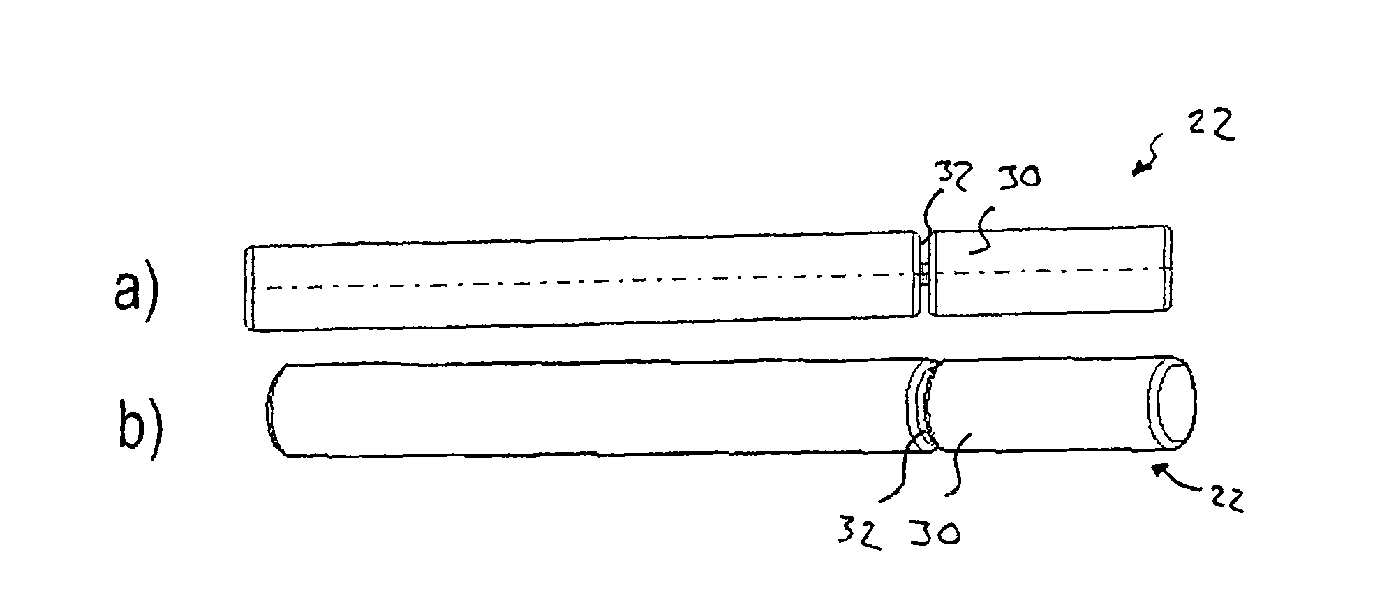
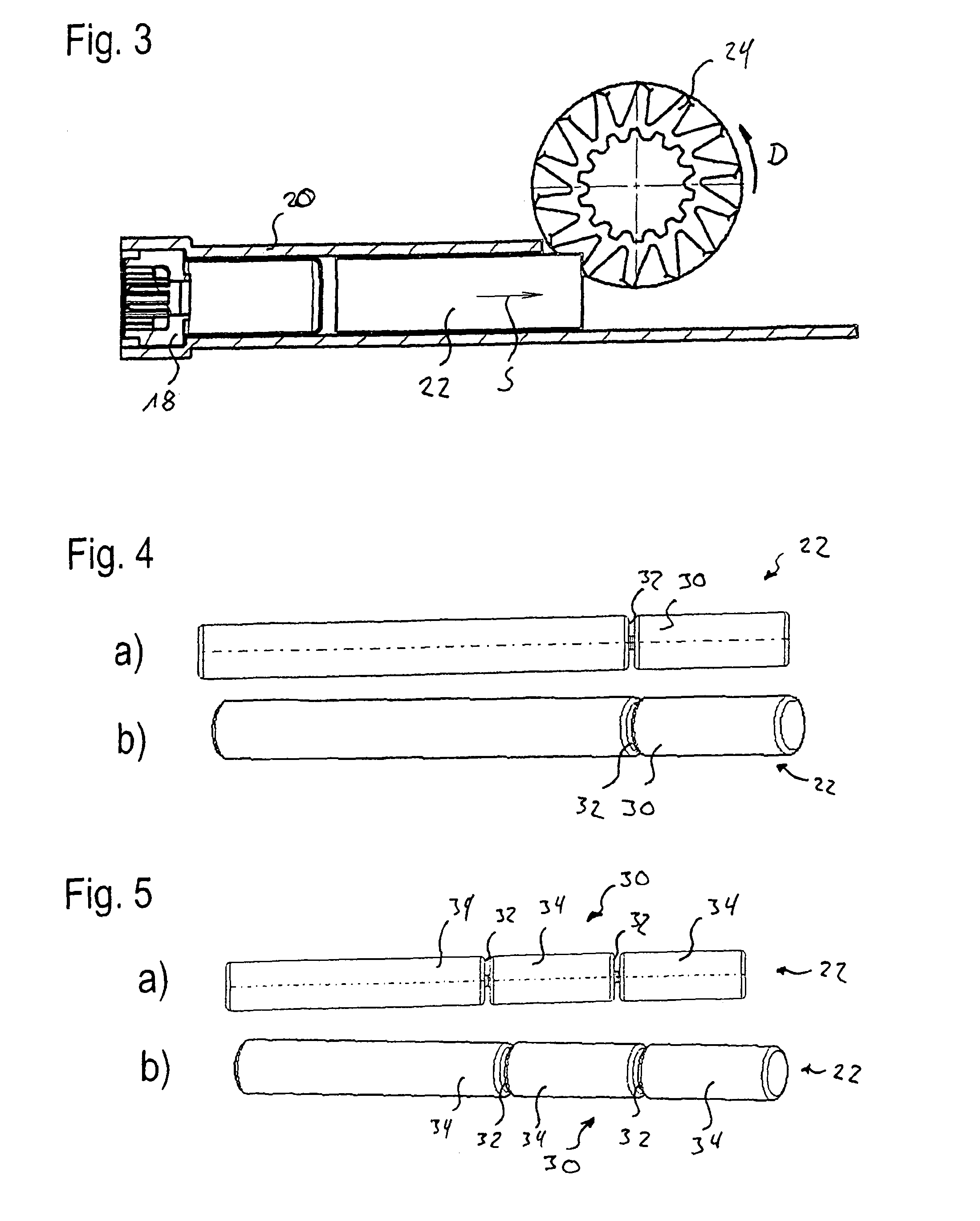
[0028]The belt tensioner 16 of the belt retractor 10 includes a pyrotechnic drive unit 18, a tensioner tube 20 having a bent tubular portion 21, a force-transmitting element 22 disposed in the tensioner tube 20 as well as a pinion gear 24 coupled to the belt reel 14. The component parts of the belt tensioner 16 are jointly arranged in a tensioner housing 26. In FIG. 1 furthermore the retracting mechanism 28 of the belt retractor 10 is shown. This mechanism is not important to the function of the belt tensioner 16 and the force-limiting device, respectively, so that it is not expl...


PUM


Abstract

In a belt retractor (10) having a belt tensioner (16) and a force-limiting device, the belt tensioner (16) includes a pivoted pinion gear (24) associated with a belt reel (14), a drive unit (18) and an oblong force-transmitting element (22) movable by the drive unit (18) supported at least partly in a tubular portion (21) and adapted to be engaged in the pinion gear (24) so as to rotate the pinion gear (24) in a tensioning direction (A). The force-transmitting element (22) includes a bending portion (30) which is provided at the rear end of the force-transmitting element (22) viewed in the tensioning direction and which is designed to be pressure-resistant in the longitudinal direction (L) of the force-transmitting element (22) but to be flexible in a direction perpendicular to the longitudinal direction (L).

Description

RELATED APPLICATIONS[0001]This application corresponds to PCT / EP2012 / 001473, filed Apr. 3, 2012, which claims the benefit of German Application No. 10 2011 016 153.8, filed Apr. 5, 2011, the subject matter of which are incorporated herein by reference in their entirety.BACKGROUND OF THE INVENTION[0002]The invention relates to a belt retractor comprising a belt tensioner and a force-limiting device, wherein the belt tensioner includes a pivoted pinion gear associated with a belt reel, a drive unit and an oblong force-transmitting element movable by the drive unit which is at least partly supported in a tubular portion and can be engaged in the pinion gear so as to rotate the pinion gear in a tensioning direction.[0003]Belt retractors usually include a belt tensioner adapted to counteract a belt slack of the seat belt and a film-spool effect of the seat belt wound on the belt reel. Such belt tensioner comprises, e.g., a pivoted pinion gear coupled to the belt reel, a drive unit and a ...

Claims


Application Information

Patent Timeline
Patent Type & Authority Applications(United States)
IPC IPC(8): B60R22/34
CPCB60R22/34B60R22/4628B60R2022/4647
Inventor GENTNER, BERNDPREGITZER, ANDREASMOEDINGER, THOMASFRANZ, SCOTT M.
Owner TRW AUTOMOTIVE GMBH
Why Eureka
Try Eureka