
Installation device for instrumentation device of stationary engine

a technology for installing devices and stationary engines, which is applied in the direction of machines/engines, electrical control, applications, etc., can solve the problems of complicated structure of the device installation device 120, failure and malfunction the need for a space for installation, so as to improve the effect of suppressing the vibration of the instrumentation device, effectively suppressing the vibration of the opposite end portions, and avoiding the resonance between the instrumentation device and the engine fram

Active Publication Date: 2014-01-16
MITSUBISHI HEAVY IND ENGINE & TURBOCHARGER LTD
View PDF5 Cites 3 Cited by
  • Summary
  • Abstract
  • Description
  • Claims
  • Application Information

AI Technical Summary

Benefits of technology

The present invention aims to provide an instrumentation device installation device that is low-cost and effective in reducing vibration. This device is designed to be mounted on the engine frame of a stationary engine to prevent faults and malfunctions of the instrumentation device and prolong its life.

Problems solved by technology

When instrumentation devices such as a sensor and an amplifier are directly fixed to an engine frame, the vibration of the engine is transmitted to the instrumentation devices, which causes faults and malfunctions of the instrumentation devices.
However, unfavorably, the instrumentation device installation device 120 has a complicated structure, and requires a space for installation thereof, and is expensive.
Further, when the vibration frequencies of the fuel pressure sensor and the vibration isolating material disclosed in Patent Document 1 are within a resonance generation region with the vibration frequency of the engine, the resonance phenomenon occurs, and a large vibration is caused in the fuel pressure sensor.
This may cause faults or malfunction of the fuel pressure sensor.

Method used


Image

  • Installation device for instrumentation device of stationary engine
  • Installation device for instrumentation device of stationary engine
  • Installation device for instrumentation device of stationary engine

Examples


first embodiment

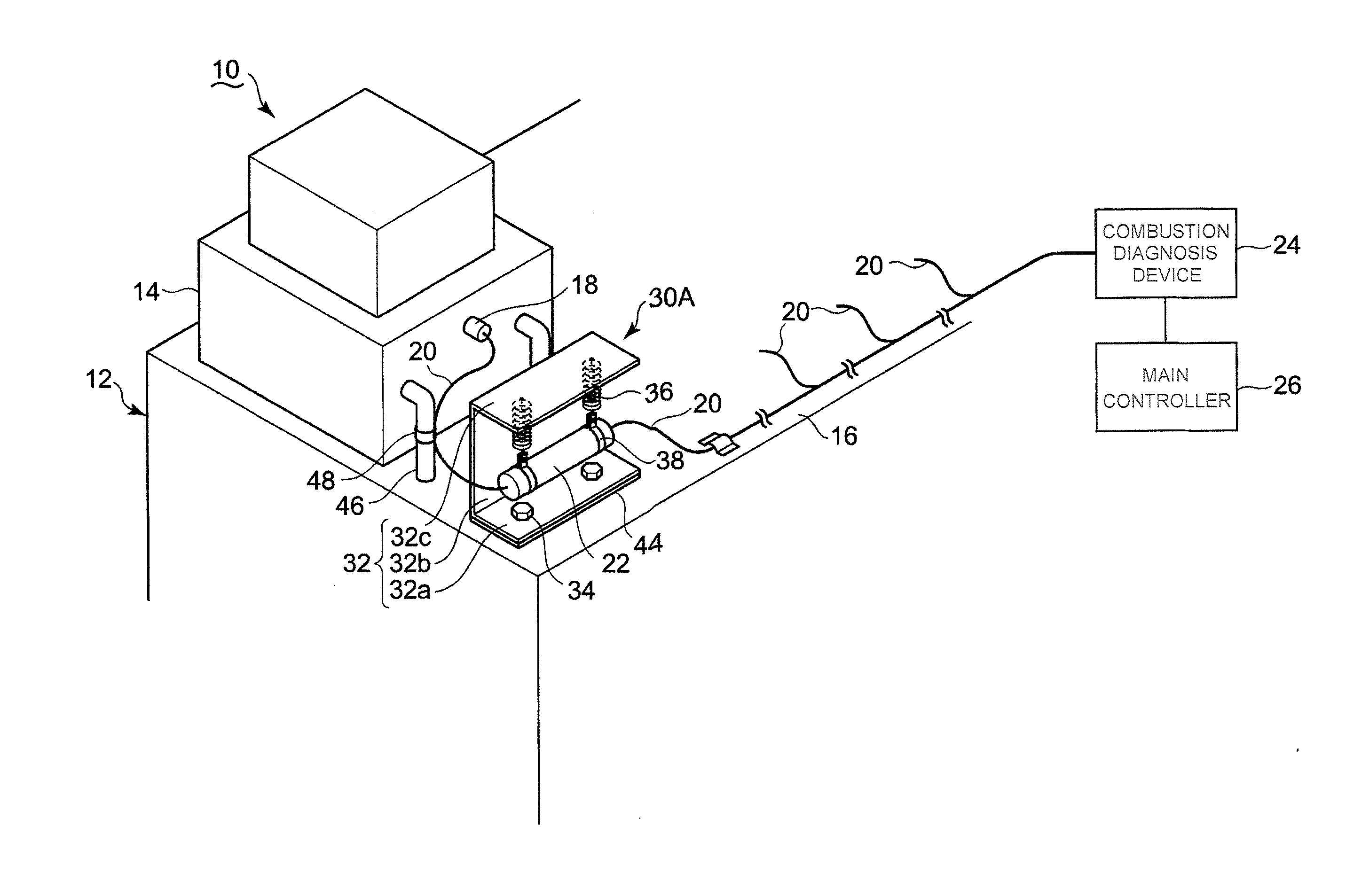
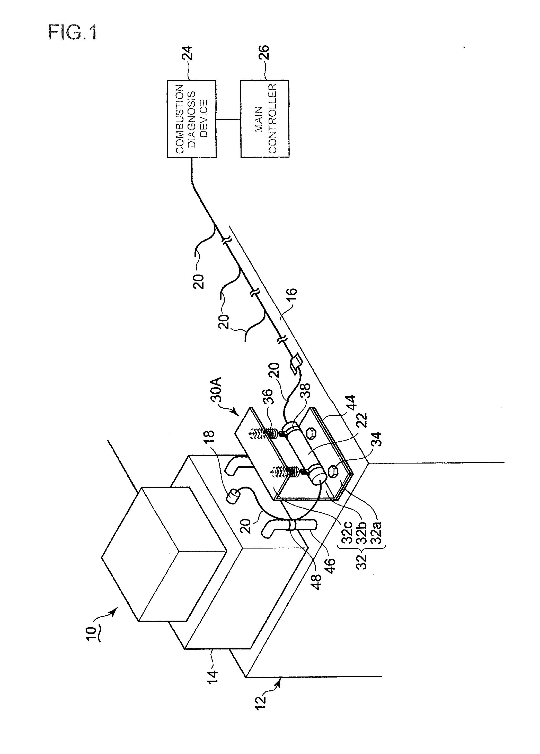
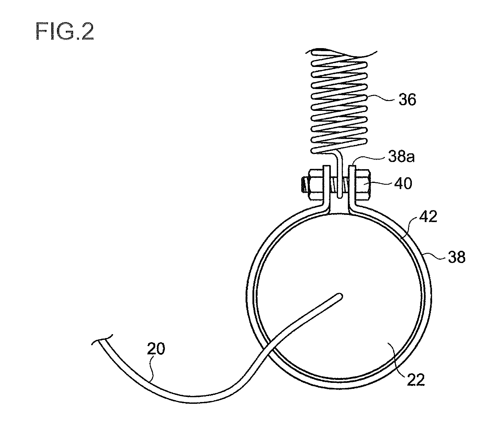
[0032]First Embodiment of the present invention device will be described by reference to FIGS. 1 and 2. In FIG. 1, a stationary gas engine 10 includes four cylinder heads 14 as with FIG. 7. However, the three cylinder heads 14 are not shown. In each cylinder head 14, there is mounted a cylinder internal pressure sensor 18 for detecting the combustion pressure in the cylinder. A lead wire 20 is connected to the cylinder internal pressure sensor 18, and an amplifier 22 is inserted at the midpoint of the lead wire 20.

[0033]The lead wire 20 is fixed by a binding band 48 on the surface of a pipeline 46 disposed at the engine frame 12 between the cylinder internal pressure sensor 18 and the amplifier 22. A detection signal from the cylinder internal pressure sensor 18 is amplified at the amplifier 22, and is sent to a combustion diagnosis device 24 via the lead wire 20. A combustion diagnosis signal from the combustion diagnosis device 24 is sent to a main controller 26 for controlling th...

second embodiment

[0040]Then, Second Embodiment of the present invention device will be described by way of FIG. 3. The present embodiment is also an example, in which the present invention is applied to the same stationary gas engine 10 as that of First Embodiment. In the present embodiment, the amplifier 22 as an instrumentation device, the suspending tool 32 forming the instrumentation device installation device 30B, and the coil spring 36 are equal in configuration to those of First Embodiment, and hence are given the same reference numerals and signs. In addition, the same members as those of First Embodiment are given the same reference numerals and signs.

[0041]In FIG. 3, the amplifier 22 is formed of a major axis cylinder body, and the lead wire 20 is connected to the opposite ends of the major axis cylinder body. Further, the amplifier 22 is held by a pair of fixing bands 50a and 50b. The fixing bands 50a and 50b are formed in a semi-circular shape, and each have flat flange parts 52a and 52b...

third embodiment

[0045]Then, Third Embodiment of the present invention device will be described by reference to FIG. 4. In an instrumentation device installation device 30C of the present invention shown in FIG. 4, the amplifier 22 formed of a major axis cylinder body is fastened and held at the vicinity of the upper end thereof by fixing bands 50a and 50b. Respective one ends of two wires 62 and 64 are respectively connected to bolts 54. The other ends of the wires 62 and 64 are connected to each other, and then connected to a coil spring 60. The other end of the coil spring 60 is connected to a suspending plate 32c. Thus, the amplifier 22 is suspended by one coil spring 60. The other configurations including those of the fixing bands 50a and 50b are the same as those of Second Embodiment.

[0046]With such a configuration, the amplifier 22 is suspended by one wire 62. For this reason, it is possible to further reduce the cost of the instrumentation device installation device 30C. In addition, it is p...


PUM


Abstract

A cylinder head of a stationary gas engine is provided with a cylinder internal pressure sensor. An engine frame is provided with an instrumentation device installation device. An amplifier for amplifying a signal detected by the cylinder internal pressure sensor is fixed to the instrumentation device installation device. The instrumentation device installation device includes a suspending tool formed of a fixing plate which is in contact with a horizontal plane and is fixed thereto by bolts, an extension plate bent at a right angle to the fixing plate, and a suspending plate bent at a right angle to the extension plate and arranged in parallel with the fixing plate, and a coil spring connected at one end thereof to the suspending plate, and connected at the other end thereof to a fixing band for holding the amplifier.

Description

TECHNICAL FIELD[0001]The present invention relates to an installation device for an instrumentation device which inhibits transmission of vibration to the instrumentation device to be mounted to the engine frame of a stationary engine, and enables prevention of faults and malfunctions of the instrumentation device.BACKGROUND ART[0002]When instrumentation devices such as a sensor and an amplifier are directly fixed to an engine frame, the vibration of the engine is transmitted to the instrumentation devices, which causes faults and malfunctions of the instrumentation devices. For this reason, when the instrumentation device is mounted to the engine frame, vibration isolating measures are required. Conventionally, there has been used, for example, a vibration isolating device as shown in FIG. 7.[0003]FIG. 7 shows an engine frame 102 of a stationary gas engine 100. The stationary gas engine 100 is provided with four cylinder heads 104. A cylinder internal pressure sensor 108 for detect...

Claims


Application Information

Patent Timeline
Patent Type & Authority Applications(United States)
IPC IPC(8): F02B77/00F02B63/00
CPCF02B77/00F02B63/00F02B77/085F02D41/0027F02D2400/21F02D19/025F02D35/023F16F15/067F02D35/00F02M55/02F02G1/055
Inventor OKUMURA, HIDEAKIMAEHATA, KIMIHIKOFURUKAWA, YUTA
Owner MITSUBISHI HEAVY IND ENGINE & TURBOCHARGER LTD
Learn More