Device and method for communication between an electronic module and a detection sensor in the presence of a light source

a technology of detection sensor and electronic module, which is applied in the field of devices and methods for communication between electronic modules and detection sensors in the presence of light sources, can solve the problem of no longer conceivable generic bcm common to all types of handles

Active Publication Date: 2014-01-16
VITESCO TECH GERMANY GMBH
View PDF7 Cites 9 Cited by
  • Summary
  • Abstract
  • Description
  • Claims
  • Application Information

AI Technical Summary

Benefits of technology

[0013]The objective of the present invention is to propose a solution which makes it possible to manage the turning on and the turning off of the light source while allowing the transmission of the information items relating to the detection of a predefined event from the detection sensor to the BCM and therefore to manage, on one and the same supply line W1, the current inrushes generated to turn on the light source and the current inrushes generated during the communication between the detection sensor and the BCM.
[0020]Thus, the communication of the information item according to which an event has been detected by the detection sensor is carried out by priority over the turning on / turning off of the LED, without creating interference.

Problems solved by technology

Now, the addition of a wire link-up between the BCM 10 and the detection sensor 20 situated in the door handle goes with problems regarding integration, because of the restricted space in the handle, problems regarding connection arrangements and cost for the BCM 10, since the latter must be specifically modified for the types of handles comprising an LED, and consequently a generic BCM common to all the types of handles is no longer conceivable.

Method used


Image

  • Device and method for communication between an electronic module and a detection sensor in the presence of a light source
  • Device and method for communication between an electronic module and a detection sensor in the presence of a light source
  • Device and method for communication between an electronic module and a detection sensor in the presence of a light source

Examples


Embodiment Construction

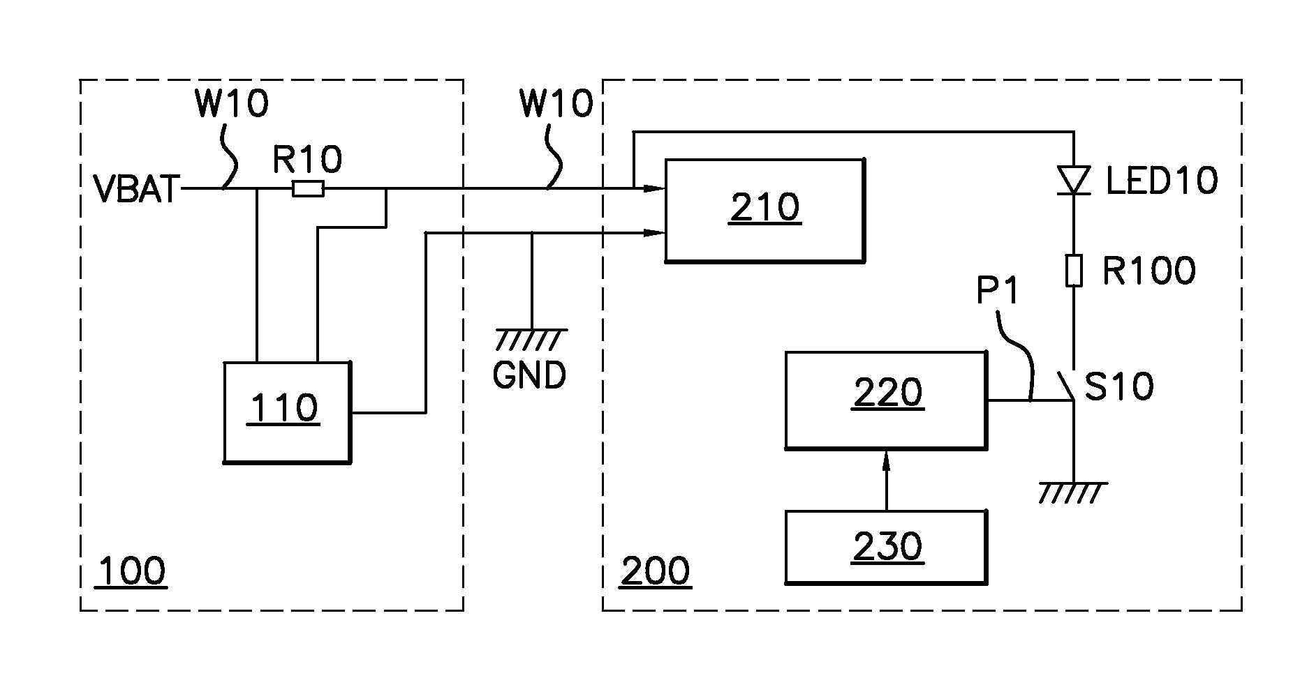
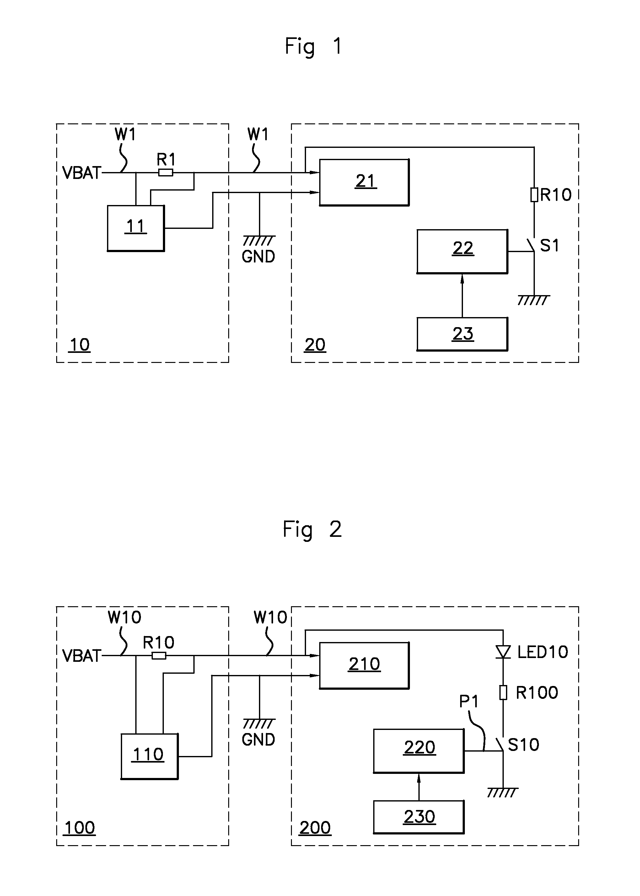
[0033]A communication device according to the invention, illustrated in FIG. 2, comprises:[0034]an electronic module 100, in our example a BCM,[0035]a capacitive detection sensor 200,[0036]a current-supply line W10 connecting the BCM 100 to the sensor 200.

[0037]The BCM 100 comprises a microcontroller 110 connected to a voltage of the battery VBAT by the current-supply line W10 and connected to a ground GND. The BCM 100 furthermore comprises a resistor R10, situated on the supply line W10, to the terminals of which the microcontroller 110 and associated electronics are connected.

[0038]The detection sensor 200 comprises:[0039]an electrical supply 210 connected directly to the voltage of the battery VBAT, via the supply line W10, and connected to the ground GND by the BCM 100,[0040]a microcontroller 220, connected to at least one capacitive electrode 230 for detecting approach and / or contact,[0041]a light source, in our example an LED LED10.

[0042]The detection sensor 200 furthermore co...


PUM


Abstract

Method for communication between an electronic module and a sensor having a light source and being supplied by supply line, the electronic module measuring the modulations of the intensity of the current in the line. The sensor drives a gradual turning on / turning off of the light source by a first modulation of the intensity of the current such that: the light source is turned off, respectively turned on, when the intensity of the current is in a low, respectively high, state, and the light source illuminates, respectively turns off, when the duty ratio of the intensity of the current varies from the high state to the low state and vice versa. During detection, the sensor dispatches a second modulation through the light source, however if the light source is turning on (or off), this is interrupted and the intensity of current is forced to the high (or low) state.

Description

FIELD OF THE INVENTION[0001]The invention relates to a device and a method for communication between an electronic module and a detection sensor. More particularly, the invention proposes a device for communication between an electronic module onboard an automotive vehicle and a sensor sited remotely from the electronic module and situated on said vehicle.BACKGROUND OF THE INVENTION[0002]Nowadays, automotive vehicles comprise several electronic modules for controlling the diverse sensors and / or actuators situated on the vehicle. Certain modules manage the sensors and / or the actuators of the power train. They are called ECU (“Engine Control Unit”). Others manage the sensors and / or actuators situated in the bodywork of the vehicle, they are called BCM (“Body Control Module”), that is to say control module relating to the sensors and / or actuators situated in the bodywork of the vehicle. The BCM thus manages in particular the approach and / or contact detection sensors situated in the doo...

Claims


Application Information

Patent Timeline
Patent Type & Authority Applications(United States)
IPC IPC(8): H05B33/08H05B44/00
CPCH05B33/0848H04B3/548H04B2203/5412H04B2203/5454H05B47/185H05B45/14
Inventor BAUDRU, STEPHANROBIN, CYRILCARNIAUX, JOEL
Owner VITESCO TECH GERMANY GMBH
Why Eureka
Try Eureka