
Quantum rod light-emitting display device

a light-emitting display and quantum rod technology, applied in the field of light-emitting display devices, can solve the problems of increasing fabrication costs, lcd has a very low light use efficiency, and the material life of blue emission materials is relatively short, so as to improve the transmittance of a polarizer, improve the field visibility, and improve the effect of polarization characteristics

Active Publication Date: 2014-01-16
LG DISPLAY CO LTD
View PDF12 Cites 9 Cited by
  • Summary
  • Abstract
  • Description
  • Claims
  • Application Information

AI Technical Summary

Benefits of technology

The technical effects of this patent include: 1) a simpler and more efficient display device than traditional LCDs, and 2) improved polarization characteristics that enhance the display's visibility. Additionally, the patent aims to improve the transmittance of the polarizer and enhance field visibility.

Problems solved by technology

In particular, a blue emission material has a relatively short lifespan, which is shorter than a lifespan of a typical display device.
However, the LCD has a very low light use efficiency because only 5 to 6% of light emitted by the BLU is substantially and finally incident to a user's eyes.
Also, since configuration of a polarizer becomes increasingly complicated to obtain desired polarization effects, fabrication cost increases.
In this instance, however, the polarizer absorbed moisture under high-temperature high-humidity conditions and generated gases in a solid to cause swelling of the solid.
In serious instances, the polarizer contracted.
As a result, failure rate of polarizer increased, thereby degrading the performance of the FPDs.

Method used


Image

  • Quantum rod light-emitting display device
  • Quantum rod light-emitting display device
  • Quantum rod light-emitting display device

Examples


Embodiment Construction

[0028]Reference will now be made in detail to the embodiments of the invention, examples of which are illustrated in the accompanying drawings.

[0029]To begin with, a quantum rod used in the embodiments of the invention will be briefly described.

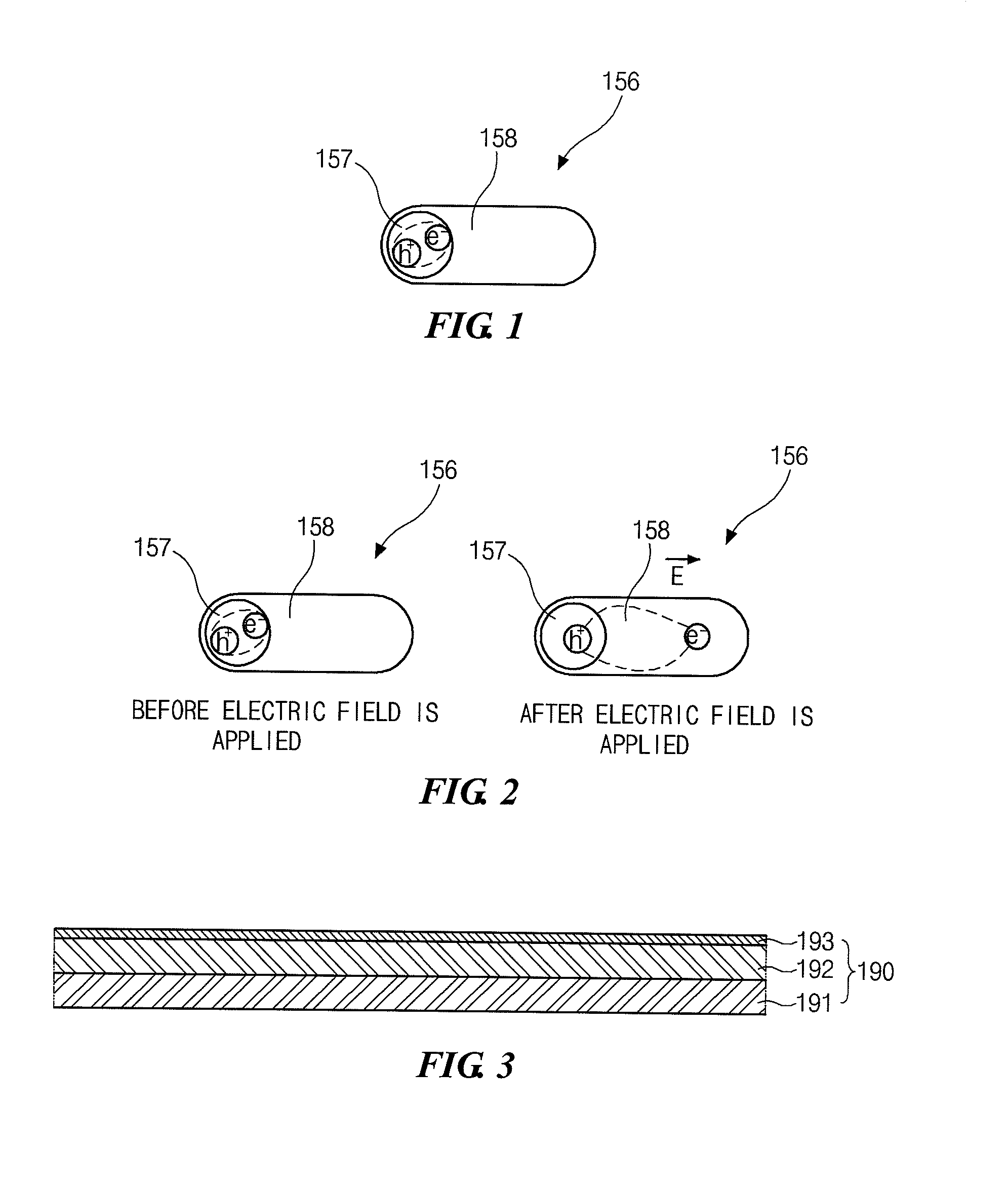
[0030]FIG. 1 illustrates a quantum rod according to an embodiment of the invention.

[0031]As shown in FIG. 1, a quantum rod 156 includes a core 157 forming a center portion of the quantum rod 156, and a shell 158 surrounding the core 157.

[0032]In an example embodiment of the invention, although the quantum rod 156 of FIG. 1 includes the core 157 and the shell 158 surrounding the core 157, the shell 158 may be omitted and the quantum rod 156 may include only the core 157.

[0033]Although FIG. 1 illustrates that the core 157 of the quantum rod 156 has a spherical shape, the core 157 may have any one of a spherical shape, an elliptical spherical shape, a polyhedral shape, and a rod shape. Other shapes may be used for the core 157. When the quantum ...


PUM


Abstract

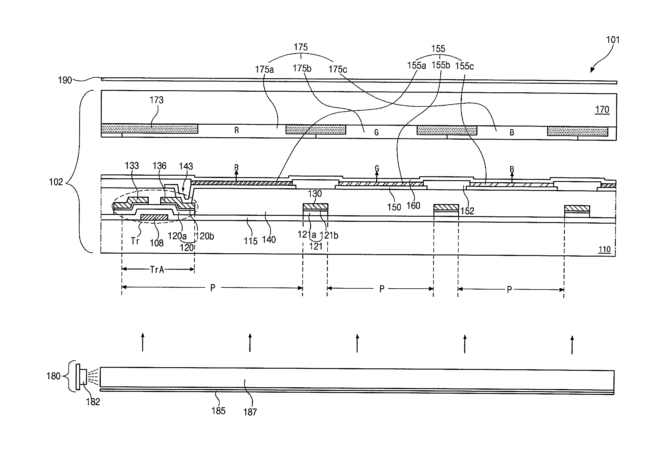
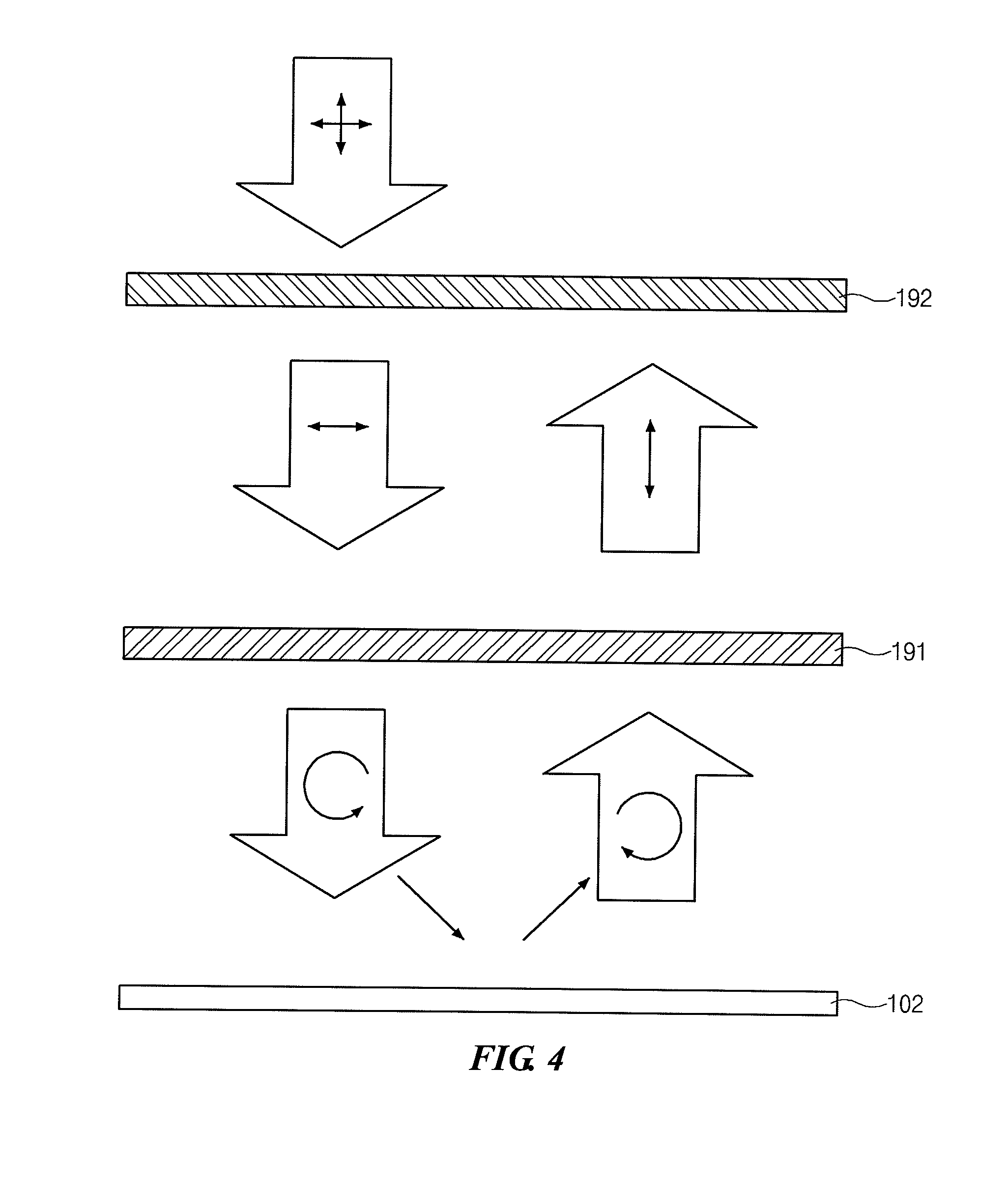
A quantum rod light-emitting display device according to an embodiment of the invention includes a display panel including a first substrate, a second substrate opposite to the first substrate, and a quantum rod layer formed between the first substrate and the second substrate, wherein a plurality of quantum rods are arranged in the quantum rod layer in one direction; and a polarizer disposed on the display panel and including a quarter wave plate (QWP) layer and a polyvinyl alcohol (PVA) layer, wherein the PVA layer transmits only light linearly polarized in a first direction, and wherein the QWP layer is disposed under the PVA layer, and the QWP layer circularly polarizes the light linearly polarized in the first direction or linearly polarizes light reflected by the display panel in a second direction.

Description

CROSS-REFERENCE TO RELATED APPLICATION[0001]This application claims priority to and the benefit of Korean Patent Application No. 10-2012-0077146 filed in Republic of Korea on Jul. 16, 2012, the disclosure of which is hereby incorporated by reference in its entirety.BACKGROUND OF THE INVENTION[0002]1. Field of the Invention[0003]Embodiments of the invention relate to a light-emitting display device, and more particularly, to a quantum rod light-emitting display device including a quantum rod layer.[0004]2. Discussion of the Related Art[0005]With gradual developments in personal computers (PCs), portable terminals, and various information apparatuses, highly efficient flat panel displays (FPDs) made lightweight and thin, and driven at low power have been required.[0006]Recently, research into an active-matrix organic light emitting diode (AMOLED) panel, which is a self-emissive display panel, has briskly been conducted. In the AMOLED panel, organic emission materials forming an organi...

Claims


Application Information

Patent Timeline
Patent Type & Authority Applications(United States)
IPC IPC(8): F21V9/14
CPCG02F2/02H05B33/02H01L33/06H01L33/24
Inventor JEON, ILKIM, KYUNG-CHANPARK, JOONG-PILLGEE, MOON-BAECHO, SUNG-HEEJANG, KYUNG-KOOKJEONG, KYUNG-SEOK
Owner LG DISPLAY CO LTD
Learn More