Polarizing element, liquid crystal device, and electronic apparatus

a technology of liquid crystal devices and polarizing elements, applied in the direction of polarizing elements, instruments, optics, etc., can solve the problems of inability to acquire sufficient brightness level, marked light degradation, and inability to achieve sufficient brightness level, etc., to achieve the effect of superior display quality

Active Publication Date: 2013-01-03
SEIKO EPSON CORP
View PDF2 Cites 5 Cited by
  • Summary
  • Abstract
  • Description
  • Claims
  • Application Information

AI Technical Summary

Benefits of technology

[0037]According to the above-described electronic apparatus, since the above-described liquid crystal device is included, an electronic apparatus including a liquid crystal display unit having a superior display quality can be realized.

Problems solved by technology

Since the polarizing glass can be configured by using only inorganic materials, compared to a polarizing plate containing organic materials, the degradation with respect to light is markedly low.
As a result, the transmittance of the polarizing element decreases, and, in a case where the polarizing element is used in a liquid crystal display device or the like, there is concern that a sufficient brightness level cannot be acquired.
As a result, there is a problem that a brightness level, contrast, and color reproducibility that are sufficient for a liquid crystal display device cannot be acquired.

Method used


Image

  • Polarizing element, liquid crystal device, and electronic apparatus
  • Polarizing element, liquid crystal device, and electronic apparatus
  • Polarizing element, liquid crystal device, and electronic apparatus

Examples


first embodiment

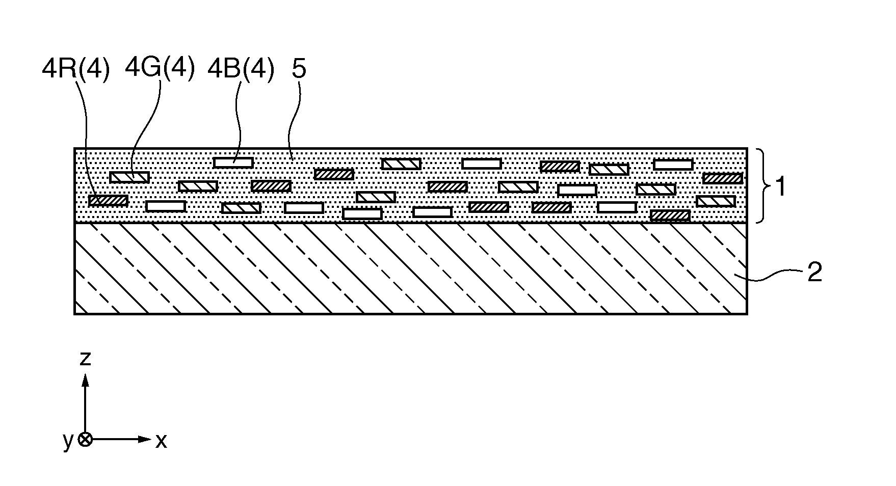
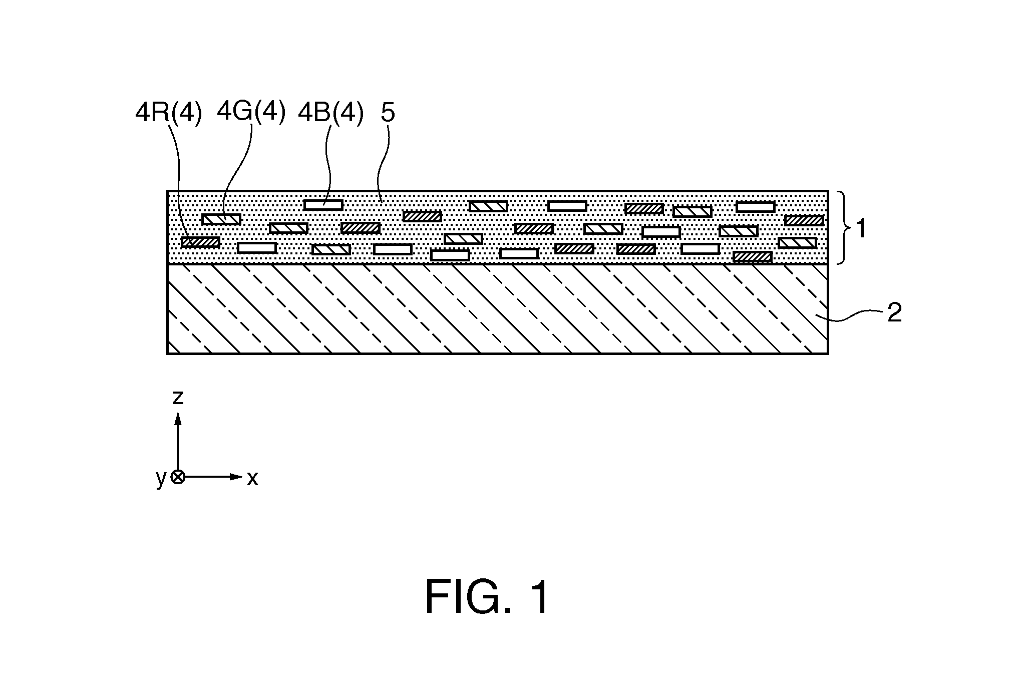
[0046]Hereinafter, a first embodiment of the invention will be described with reference to FIG. 1 and FIGS. 2A to 2C.

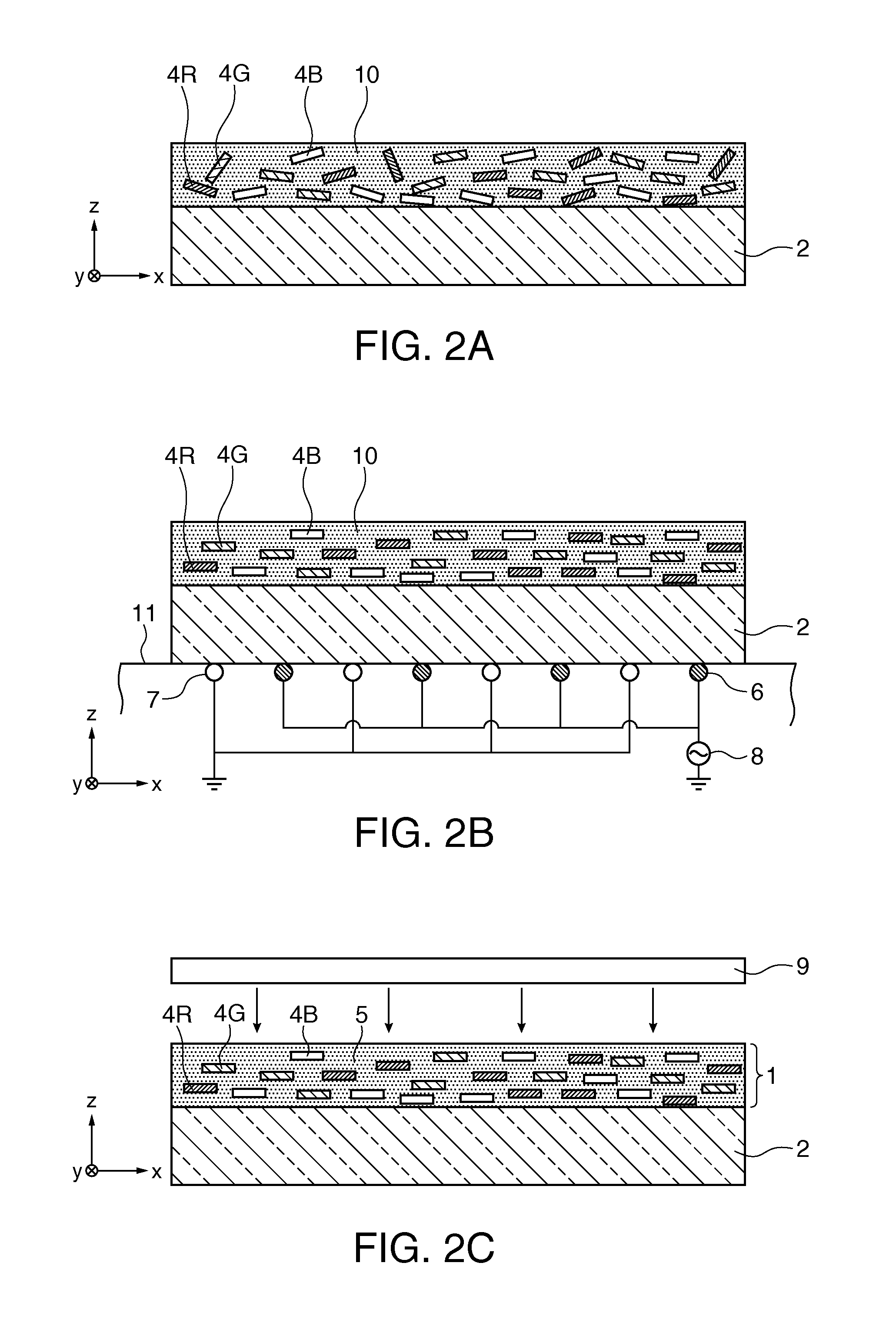
[0047]FIG. 1 is a cross-sectional view showing a polarizing element according to this embodiment. FIGS. 2A to 2C are cross-sectional views showing the process of manufacturing the polarizing element according to this embodiment in order.

[0048]In the following drawings, in order to allow each constituent element to be visually recognized in an easy manner, the scale of the size of the constituent element may be differently illustrated.

[0049]The polarizing element 1 according to this embodiment, as shown in FIG. 1, is supported by a glass substrate 2 as a base material. A specific material of the glass substrate 2 is not particularly limited, and any type of known glass substrate may be used. In addition, as long as the substrate has a light transmitting property, it is not limited to a glass substrate, and a quartz crystal substrate, a sapphire substrate, a resin subst...

second embodiment

[0072]Hereinafter, a second embodiment of the invention will be described with reference to FIG. 3.

[0073]The basic configuration of the polarizing element according to this embodiment is similar to that according to the first embodiment, but only the configuration of the polarizing layer is different from that of the first embodiment.

[0074]FIG. 3 is a cross-sectional view showing the polarizing element according to this embodiment.

[0075]In FIG. 3, the same reference numeral is assigned to the constituent element that is common to that of the first embodiment shown in FIG. 1, and detailed description thereof will not be presented here.

[0076]As the polarizing element 1 according to the first embodiment, the polarizing element 1 of one layer is formed on the glass substrate 2. In contrast to this, the polarizing element 21 according to this embodiment, as shown in FIG. 3, includes a glass substrate 2 (base material) as a base material and a polarizing layer 12B, a polarizing layer 12G,...

third embodiment

[0080]Hereinafter, a third embodiment of the invention will be described with reference to FIG. 4.

[0081]The basic configuration of the polarizing element according to this embodiment is similar to that according to the second embodiment, but only the configuration of the third polarizing layer is different from that of the second embodiment.

[0082]FIG. 4 is a cross-sectional view showing the polarizing element according to this embodiment.

[0083]In FIG. 4, the same reference numeral is assigned to the constituent element that is common to that of the second embodiment shown in FIG. 3, and detailed description thereof will not be presented here.

[0084]The polarizing element 23 according to this embodiment, as shown in FIG. 4, includes a glass substrate 2 (base material) as a base material and a polarizing layer 12B, a polarizing layer 12G, and a polarizing layer 13R that are stacked on one face of the glass substrate 2. A first polarizing layer 12B, a second polarizing layer 12G, and a ...


PUM

PropertyMeasurementUnit
softening pointaaaaaaaaaa
viscosityaaaaaaaaaa
temperatureaaaaaaaaaa

Abstract

A polarizing element includes a plurality of first needle-shaped particles that have transmittance for first polarized light, which is in a first polarization state, that is different from transmittance for second polarized light, which is in a second polarization state different from the first polarization state, in a first wavelength region and a plurality of second needle-shaped particles that have transmittance for the first polarized light that is different from transmittance for the second polarized light, in a second wavelength region different from the first wavelength region.

Description

[0001]The entire disclosure of Japanese Patent Application No. 2011-146016, filed Jun. 30, 2011 is expressly incorporated by reference herein.BACKGROUND[0002]1. Technical Field[0003]The present invention relates to a polarizing element, a liquid crystal device, and an electronic apparatus.[0004]2. Related Art[0005]As one type of polarizing element, polarizing glass is known. Since the polarizing glass can be configured by using only inorganic materials, compared to a polarizing plate containing organic materials, the degradation with respect to light is markedly low. Thus, the polarizing glass has attracted attention in recent years as an optical device that is useful for a liquid crystal projector in which luminance increases are progressing.[0006]As general polarizing glass, polarizing glass disclosed in JP-A-56-169140 is known. A method of manufacturing the polarizing glass is as follows.[0007](1) A glass product having a desired shape is produced from a composition that contains...

Claims


Application Information

Patent Timeline
Patent Type & Authority Applications(United States)
IPC IPC(8): G02B5/30G02F1/1335
CPCG02B5/3058G02F1/133528G02F2202/36G02F2001/133538G02F1/133533G02F1/133538
Inventor KUMAI, YOSHITOMO
Owner SEIKO EPSON CORP
Why Eureka
Try Eureka