
"method and apparatus for measuring system signal"

a signal and system technology, applied in the field of system signal measurement method and apparatus, can solve the problems of paging reception failure, delay in cell reselection determination, and limited m2m communication and related market, so as to avoid failure of connection setup or missing sms message, and reflect the adjacent environment quickly.

Active Publication Date: 2014-01-16
SAMSUNG ELECTRONICS CO LTD
View PDF3 Cites 14 Cited by
  • Summary
  • Abstract
  • Description
  • Claims
  • Application Information

AI Technical Summary

Benefits of technology

This patent presents a system and method to measure signals quickly and efficiently in a network. It also explains how a machine-to-machine device can quickly select the best network to avoid connection failures or missed messages in a bad network environment.

Problems solved by technology

In the early 1990s when the concept of M2M communication has been introduced, the remote control and telematics are considered as the examples of M2M communication and the related market has been also very limited.
7. The battery-powered M2M device is required to consume the battery efficiently because it may not allowed for changing the battery frequently.
That is, even when aggregating multiple radio channel measurement results to determine cell reselection in the bad channel environment, the cell reselection determination is also delayed due to the long radio channel measurement period.
This may cause a problem of paging reception failure for several DRX periods.

Method used


Image

  • "method and apparatus for measuring system signal"
  • "method and apparatus for measuring system signal"
  • "method and apparatus for measuring system signal"

Examples


first embodiment

[0045]FIG. 5 is a flowchart illustrating the signal measurement procedure of the M2M terminal according to the present invention.

[0046]Referring to FIG. 5, the M2M terminal determines whether it is operating in the DRX mode at step 501. If it is not in DRX mode, the terminal performs the operation as specified in legacy LTE. Since the legacy LTE operation is well-known, detailed description thereon is omitted herein. If the terminal is operating in DRX mode, the procedure goes to step 502.

[0047]The M2M terminal determines whether the subframe k corresponds to the signal measurement period at step 502. If the subframe k does not correspond to the signal measurement period, the terminal performs the operation specified in the legacy LTE. If the subframe k corresponds to the signal measurement period in DRX mode, the procedure goes to step 503.

[0048]The M2M terminal performs signal measurements for neighbor eNBs at step 503. Next, the terminal performs filtering by reflecting a certain...

second embodiment

[0053]FIG. 6 is a flowchart illustrating the signal measurement procedure of the M2M terminal according to the present invention.

[0054]Referring to FIG. 6, the M2M terminal determines whether it operates in the DRX mode at step 601. If it is not in the DRX mode, the terminal performs the operation specified in the legacy LTE. Since the legacy LTE operation is well-known, detailed description thereon is omitted herein. If the terminal is operating in DRX mode, the procedure goes to step 602.

[0055]The M2M terminal determines whether the subframe k corresponds to the signal measurement period at step 602. If the subframe k does not correspond to the signal measurement period, the terminal performs the operation specified in the legacy LTE. If the subframe k corresponds to the signal measurement period in DRX mode, the procedure goes to step 603.

[0056]The M2M terminal performs signal measurements for neighbor eNBs at step 603. Next, the terminal performs filtering by reflecting a certai...


PUM


Abstract

The present invention relates to a method and apparatus for measuring a signal. According to one embodiment of the present invention, a signal measuring method may comprise the steps of: determining whether or not a current subframe corresponds to a measurement period; measuring a serving cell signal when the current subframe corresponds to the measurement period; determining whether a current measurement mode is a normal scan mode or a short scan mode in which a serving cell signal is more frequently measured than in the normal scan mode; determining whether or not the measured serving cell signal is less than a preset low signal threshold value when the current measurement mode is the normal scan mode; and changing the current measurement mode to the short scan mode when the measured serving cell signal is less than the low signal threshold value. According to one embodiment of the present invention, a system signal measuring method and apparatus which can quickly reflect the surrounding environment while efficiently using power is provided.

Description

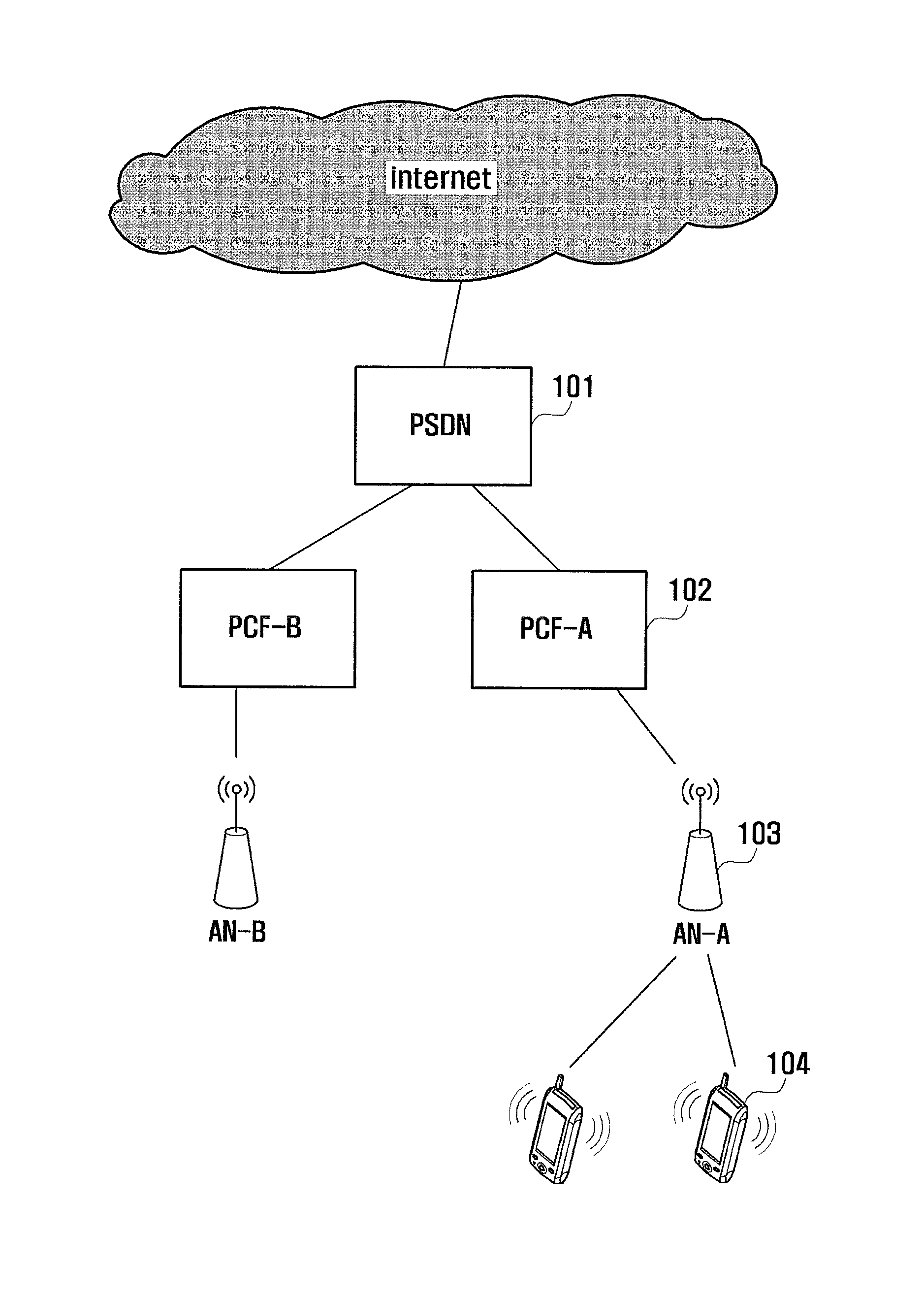
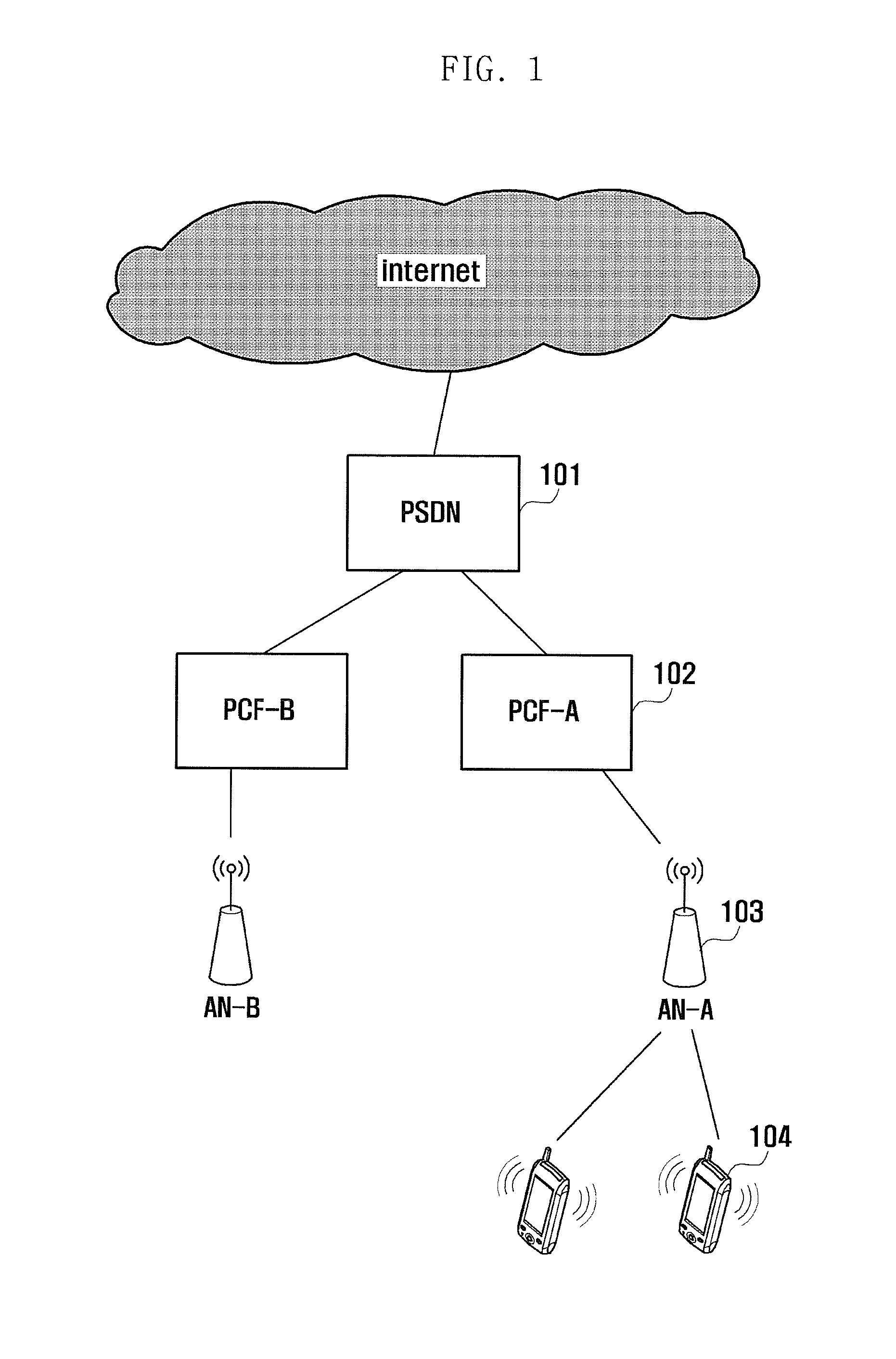
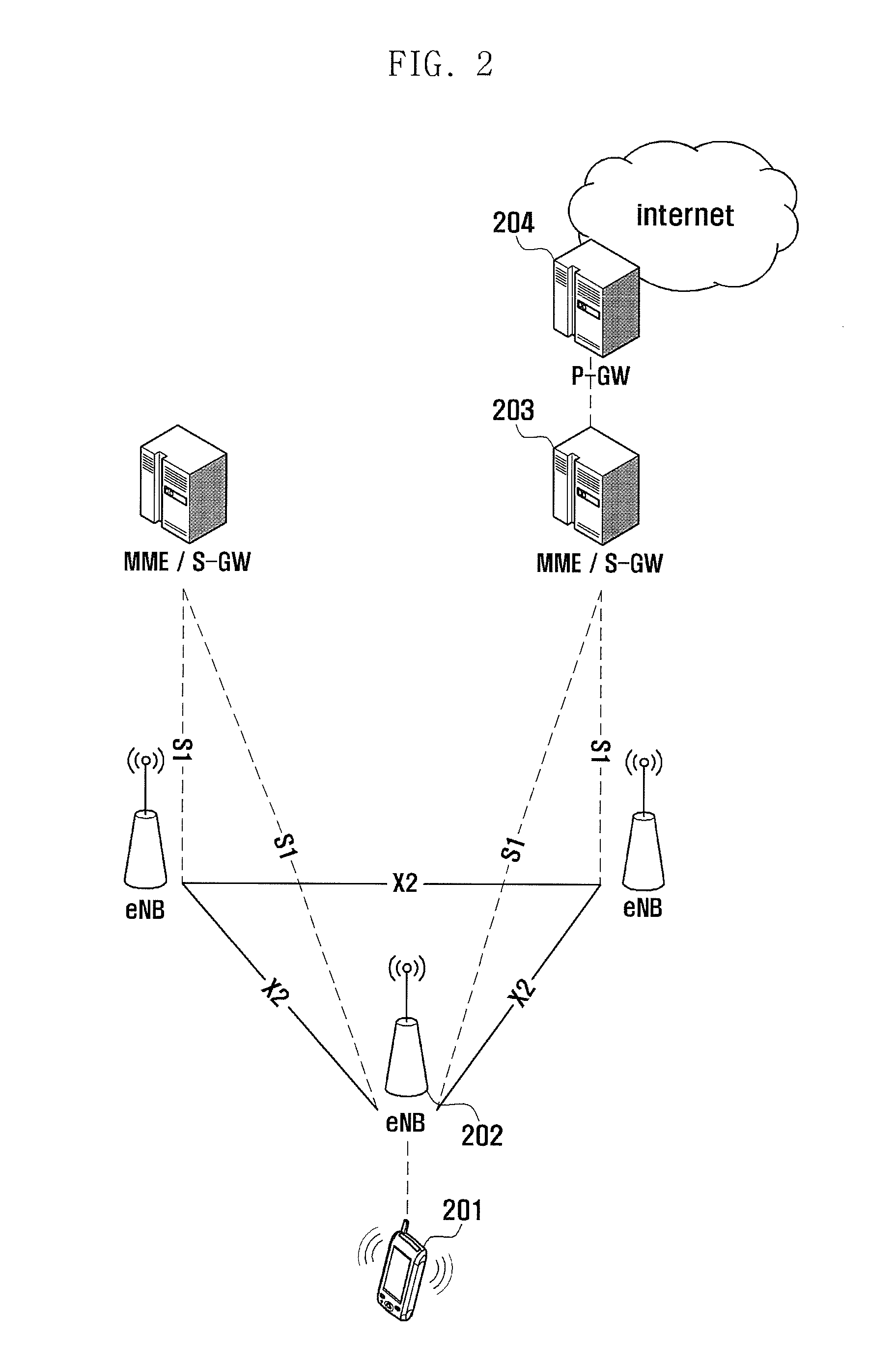
BACKGROUND OF THE INVENTION[0001]1. Field of the Invention[0002]The present invention relates to a system signal measurement method and apparatus.[0003]2. Description of the Related Art[0004]The mobile communication systems targeted by the present invention may include the 1st Generation analog, the 2nd Generation digital, the 3rd Generation IMT-2000 high speed multimedia service, and the 4th Generation ultrahigh speed multimedia service mobile communication systems.[0005]Among the 3rd generation mobile communication systems, CDMA HRPD (High Rate Packet Data) system and WCDMA HSPA (High Speed Packet Access) are representative mobile communication systems having the channel formats for high data rate. The CDMA HRPD system is the system using Code Division Multiple Access (CDMA).[0006]FIG. 1 is a diagram illustrating architecture of conventional HRPD system.[0007]The HRPD system includes a Packet Data Service Node (PDSN) 101 connected to the Internet for transmitting high speed packet...

Claims


Application Information

Patent Timeline
Patent Type & Authority Applications(United States)
IPC IPC(8): H04W52/02
CPCH04W52/0225H04W24/10Y02D30/70H04B17/21H04W24/02H04W52/0251
Inventor JUNG, JUNG SOOKIM, SOENG HUNJEONG, KYEONG INKIM, SANG BUM
Owner SAMSUNG ELECTRONICS CO LTD
Learn More