
Power supply modulator and wireless communication apparatus including the same

a technology of wireless communication and power supply, applied in the direction of power management, wireless communication, high-level techniques, etc., can solve the problems of additional power loss of rf power amplifiers, low power efficiency of existing rf power amplifiers operating with fixed power supplies such as batteries, and difficulty in meeting all requirements, so as to improve the performance of modulation operation and efficiently use power

Active Publication Date: 2020-05-05
SAMSUNG ELECTRONICS CO LTD
View PDF13 Cites 7 Cited by
  • Summary
  • Abstract
  • Description
  • Claims
  • Application Information

AI Technical Summary

Benefits of technology

This patent describes a power supply modulator that can efficiently use power and improve the performance of modulation operations. Additionally, this patent describes a wireless communication device that includes this power supply modulator. The technical effect of this invention is to enhance the performance and efficiency of wireless communication devices.

Problems solved by technology

Therefore, an RF / analog power amplifier for a wireless communication apparatus is required to satisfy all of the above requirements, but it is difficult to satisfy all of the requirements due to the limitation in a process and a circuit structure.
However, a high PAPR characteristic requires a high 1-dB gain compression point (P1 dB) and saturated power of the RF power amplifier, and thus, an existing RF power amplifier operating with a fixed power supply such as a battery has low power efficiency in both peak power and back-off power regions.
However, when employing the APT technology, the power supply voltage cannot instantaneously follow an envelope signal, and accordingly, an RF power amplifier has additional power loss.
However, when the hybrid structure is used, it is difficult to maintain a voltage of both terminals of a coupling circuit connected between the linear regulator and the switching regulator at a certain level due to a floating state, surrounding noise, and the like, and thus, an effective modulation operation cannot be performed.

Method used


Image

  • Power supply modulator and wireless communication apparatus including the same
  • Power supply modulator and wireless communication apparatus including the same
  • Power supply modulator and wireless communication apparatus including the same

Examples


Embodiment Construction

[0025]Hereinafter, example embodiments will be described in detail with reference to the accompanying drawings.

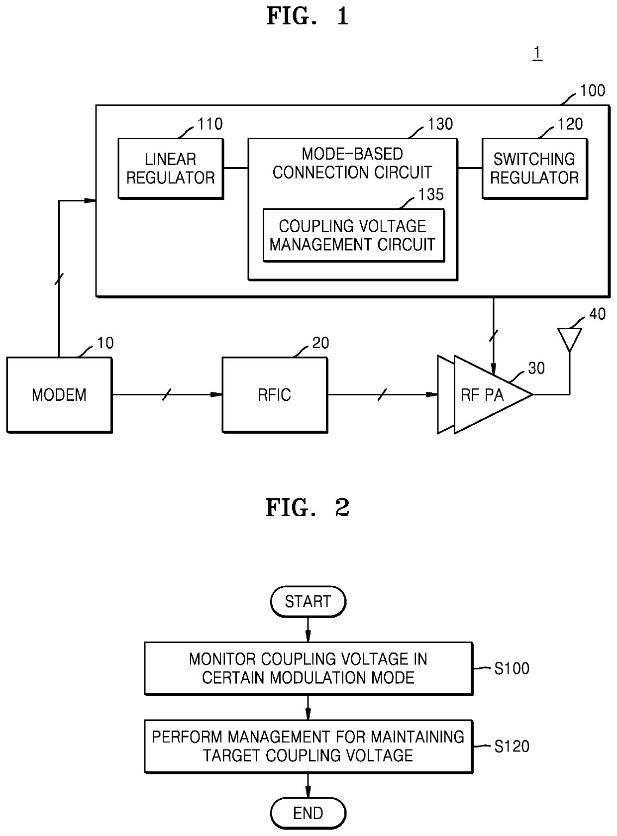
[0026]FIG. 1 is a block diagram of a wireless communication apparatus 1 including a power supply modulator 100, according to an example embodiment.

[0027]Referring to FIG. 1, the wireless communication apparatus 1 may include a modem 10, a radio frequency integrated circuit (RFIC) 20, an RF power amplifier 30, and the power supply modulator 100. The modem 10 may provide, to the RFIC 20, a transmission signal including information to be transmitted. The modem 10 may provide, to the power supply modulator 100, an envelope signal generated through amplitude modulation of the transmission signal. In this case, the power supply modulator 100 may operate in a plurality of modulation modes, and the modem 10 may provide, to the power supply modulator 100, a modulation mode control signal for modulation mode control.

[0028]The RFIC 20 may output an RF signal by modulating the transmis...


PUM


Abstract

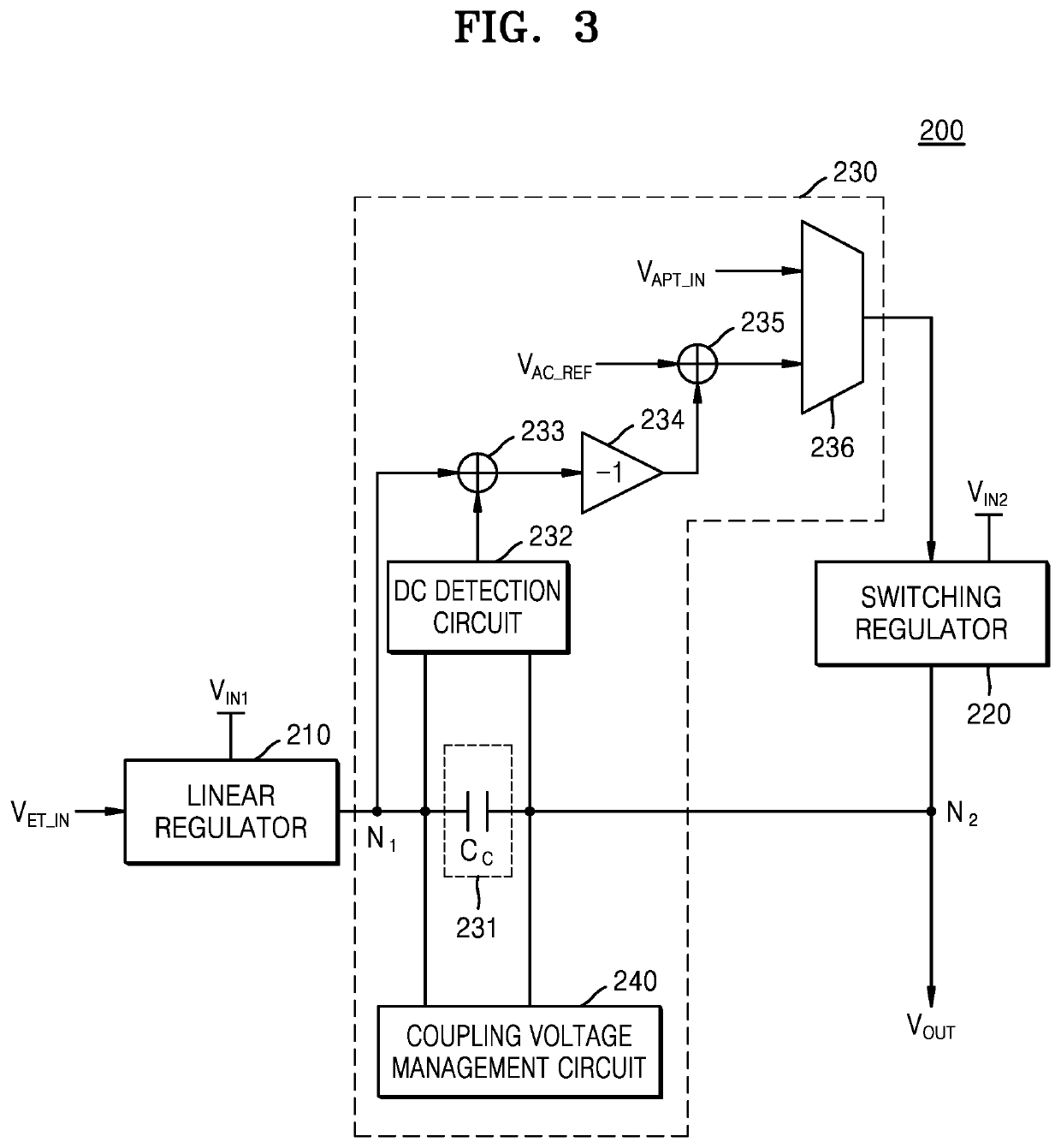
A power supply modulator includes: a linear regulator; a switching regulator; and a mode-based connection circuit. The mode-based connection circuit includes a coupling circuit configured to drop an output signal of the linear regulator by a target coupling voltage in an envelope tracking (ET) modulation mode; and a coupling voltage management circuit configured to monitor a coupling voltage of the coupling circuit in another modulation mode, and selectively apply a voltage to the coupling voltage based on a monitoring result such that the coupling voltage is maintained at the target coupling voltage.

Description

CROSS-REFERENCE TO THE RELATED APPLICATION[0001]This application claims priority from Korean Patent Application No. 10-2019-0000859, filed on Jan. 3, 2019, in the Korean Intellectual Property Office, the disclosure of which is herein incorporated by reference in its entirety.BACKGROUND1. Field[0002]One or more example embodiments relate to a power supply modulator of a wireless communication apparatus used in a wireless communication system, and a wireless communication apparatus including the same.2. Description of the Related Art[0003]In a wireless communication apparatus, particularly, a portable terminal, in which battery power consumption is important, a highly efficient radio frequency (RF) / analog power amplifier for a long battery use time is needed. Recently, wireless communication has been evolved to next-generation communication technology, thereby demanding a technique capable of obtaining a high-efficiency characteristic even in a high peak-to-average power ratio (PAPR) ...

Claims


Application Information

Patent Timeline
Patent Type & Authority Patents(United States)
IPC IPC(8): H04W52/02H03F1/02H03F3/24H04B1/40
CPCH04W52/0261H03F3/24H03F1/0222H03F2200/451H03F2200/102H04B1/40H03F2200/105H03F3/20H03F3/189Y02D30/70H03F1/0227H03F3/195H03F3/245
Inventor KIM, DONG-SUBANG, JUN-SUK
Owner SAMSUNG ELECTRONICS CO LTD
Learn More