Mold machining method and mold machining system for computer numerical control

a technology of computer numerical control and mold machining, which is applied in the direction of program control, total factory control, instruments, etc., can solve the problems of uneven refraction angle, obvious tool marks on the product made by the mold, and uneven gloss of the product, so as to reduce labor hours and enhance economic benefits , the effect of high gloss

Inactive Publication Date: 2014-01-16
WISTRON CORP
View PDF4 Cites 6 Cited by
  • Summary
  • Abstract
  • Description
  • Claims
  • Application Information

AI Technical Summary

Benefits of technology

The present invention relates to a method for achieving precision machining of three-dimensional patterns on products with minimal tool markings. By breaking down the pattern into multiple sections based on their size and shape, the machine uses different tools to change positions along the boundaries of these sections. This results in smooth transitions from one section to another, reducing any visible signs of wear and tear caused by the use of the machines' own tools. Additionally, this approach allows for faster production times and reduces the amount of manual work required, making it more efficient and cost-effective compared to other methods.

Problems solved by technology

The technical problem addressed in this patent text is the appearance of cutting marks, tool marks, and uneven surfaces on a plastic injection mold caused by the conventional CNC machining process. These issues require additional processing and increase labor hour and cost while also reducing the appearance of high gloss on the product made by the mold.

Method used


Image

  • Mold machining method and mold machining system for computer numerical control
  • Mold machining method and mold machining system for computer numerical control
  • Mold machining method and mold machining system for computer numerical control

Examples


Embodiment Construction

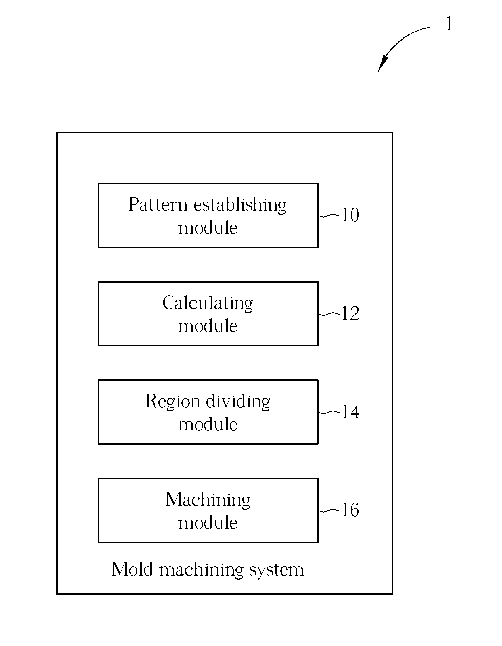
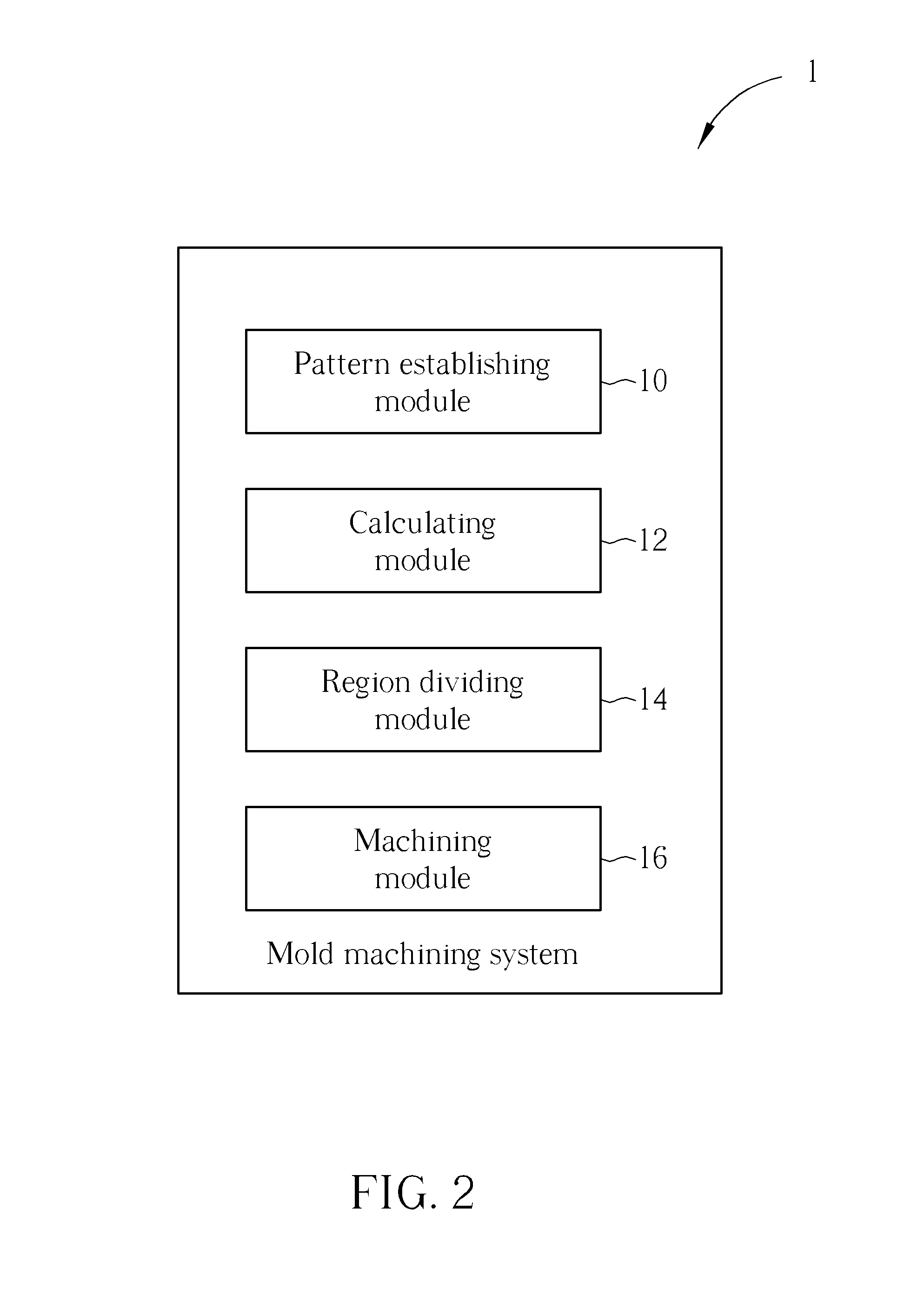
[0031]Referring to FIGS. 2 to 4, FIG. 2 is a functional block diagram illustrating a mold machining system 1 for computer numerical control according to an embodiment of the disclosure, FIG. 3 is a flowchart illustrating a mold machining method for computer numerical control according to an embodiment of the disclosure, and FIG. 4 is a schematic diagram illustrating a 3D pattern 3. The mold machining method shown in FIG. 3 can be implemented by the mold machining system 1 shown in FIG. 2. In practical applications, the mold machining system 1 shown in FIG. 2 and the mold machining method shown in FIG. 3 can be embedded in a computer numerical control (CNC) machine.

[0032]As shown in FIG. 2, the mold machining system 1 comprises a pattern establishing module 10, a calculating module 12, a region dividing module 14 and a machining module 16. In this embodiment, the pattern establishing module 10, the calculating module 12, the region dividing module 14 and the machining module 16 may b...


PUM


Abstract

A mold machining method for computer numerical control includes steps of establishing a 3D pattern; performing an initial machining process on a mold material by the 3D pattern; calculating a total machining area corresponding to the 3D pattern; dividing the 3D pattern into a plurality of precise machining regions according to the total machining area and a predetermined machining area and enabling a boundary line between every two adjacent precise machining regions to be corresponding to a crest line of the 3D pattern; and performing a precise machining process on each of the precise machining regions and changing a cutting tool at the boundary line between every two adjacent precise machining regions.

Description


Claims


Application Information

Patent Timeline
Owner WISTRON CORP
Why Eureka
Try Eureka