Pick having bimetal structure and preparation method thereof

A bimetallic and pick technology, applied in cutting machinery and other directions, can solve the problems of long service life, peeling, falling off, etc., and achieve the effect of improving wear resistance and impact resistance, good hardness and toughness, and improving service life

Inactive Publication Date: 2010-07-28
TAIYUAN UNIV OF TECH +1
View PDF0 Cites 10 Cited by
  • Summary
  • Abstract
  • Description
  • Claims
  • Application Information

AI Technical Summary

Problems solved by technology

The pick bears a lot of impact during work, and it is difficult to ensure sufficient bending strength between the weld seam and the spigot, which will cause the separation of the top of the tooth head from the rest of the tooth body; although low temperature tempering can eliminate the welding at the joint stress, but does not increase the flexural strength of welds and spigot connections
The second method is: the top of the tooth head is welded with a cemented carbide head, and the surface of the tooth head is baked with a cemented carbide layer by powder metallurgy process. If the axial force is large, a large bending stress will be generated, and the strength difference between the tooth head and the hard alloy layer is large, which will cause it to fall off, and the hard alloy head will lose its protection.
Although this layer has high hardness and can resist wear, but due to the large difference in mechanical properties between the tooth head and the wear-resistant layer, the inside is soft and the outside is hard, and the wear-resistant layer peels off due to insufficient impact resistance; in addition, because there is no hard Alloy head, the thin wear-resistant layer at the top of the tooth head alone is not enough to directly cut the coal seam and rock formation to maintain a long service life
[0004] It can be seen that the purpose of the above structures is to improve the hardness and wear resistance of the tooth head part of the pick to protect the carbide head, but the key problem is that there is an obvious interface between this reinforced part and the metal material of the original tooth body due to the large performance difference. There is no transition area between two different metal materials, and there is no real fusion with the metal material of the tooth body at the joint. It is easy to break or peel off under strong impact, which will cause the carbide head to lose its wrapping and support and be thrown out. Final pick scrapped

Method used

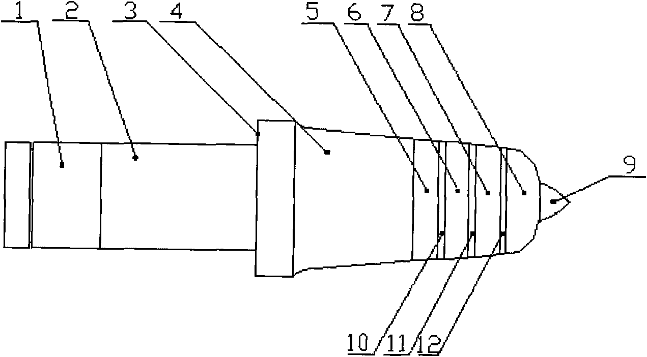
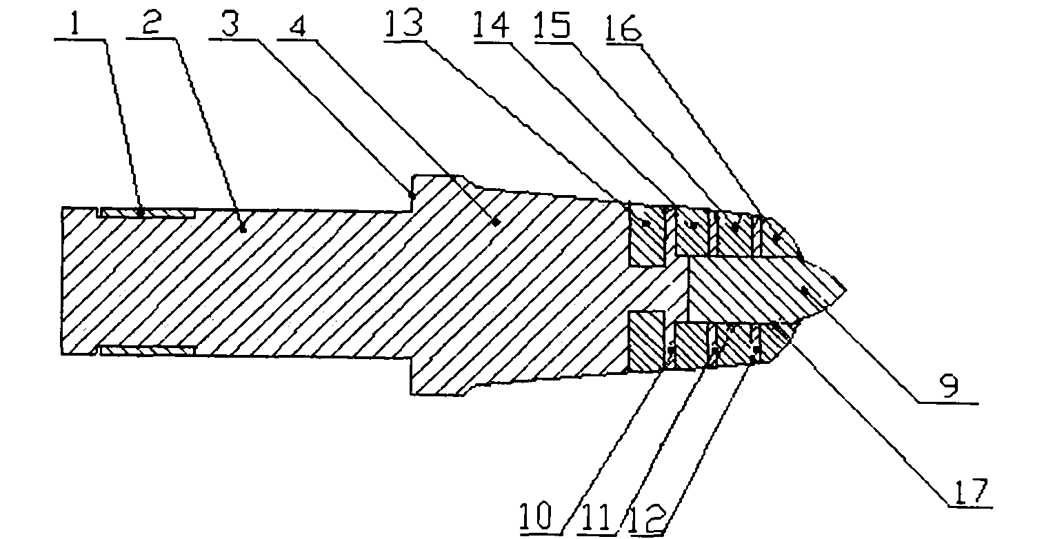
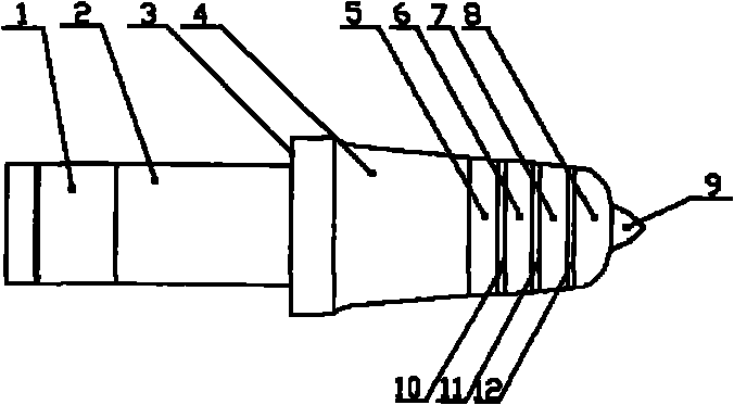

Image

  • Pick having bimetal structure and preparation method thereof
  • Pick having bimetal structure and preparation method thereof
  • Pick having bimetal structure and preparation method thereof

Examples


Embodiment approach 1

[0035] I. According to the weight percentage of the chemical composition of the deposited metal C: 0.46, Cr: 4.0, W: 6.0, Mo: 2.3, V: 0.6, Si: 0.18, Mn: 0.17, Ni: 0.50, S: 0.030, P: 0.028 Special alloy steel electrode, dried at 240°C for 2.5 hours;

[0036] II. The tooth body is machined into a cylindrical tooth shank 2 and a conical tooth head 4 by using medium carbon alloy steel;

[0037] III. Open 3 annular grooves downwards at the top of the conical tooth head 4 of the tooth body obtained in the above II. The net width of the annular grooves is 7 millimeters, and the interlayer between two adjacent annular grooves is 1.5 millimeters. The conical teeth The depth of the first annular groove downwards from the top of the head 4 is 5.5 mm, and the depth of the remaining annular grooves is deepened to 8 mm as the conical shape of the tooth head increases. The range of the annular grooves is larger than the bottom surface of the carbide head 9. The distance between the top of t...

Embodiment approach 2

[0043] I. According to the weight percentage of the chemical composition of the deposited metal C: 0.52, Cr: 5.0, W: 8.5, Mo: 2.65, V: 0.95, Si: 0.19, Mn: 0.18, Ni: 0.55, S: 0.0325, P: 0.029 Special alloy steel electrode, dried at 250°C for 2.25 hours;

[0044] II adopts medium-carbon alloy steel to be machined into a tooth body consisting of a cylindrical tooth shank 2 and a conical tooth head 4;

[0045] III. Open 4 annular grooves downwards at the top of the conical tooth head 4 of the tooth body obtained in the above II. The net width of the annular grooves is 8 millimeters, and the interlayer between two adjacent annular grooves is 1.75 millimeters. The conical teeth The depth of the first annular groove downwards from the top of the head 4 is 5.75 mm, and the depth of the remaining annular grooves is deepened to 8.5 mm as the conical shape of the tooth head increases. The distance between the top of the tooth head 4 and the last annular groove A 5 from the bottom 3 of t...

Embodiment approach 3

[0051] I. According to the weight percentage of the chemical composition of the deposited metal C: 0.58, Cr: 6.0, W: 11.0, Mo: 3.0, V: 1.3, Si: 0.20, Mn: 0.19, Ni: 0.60, S: 0.035, P: 0.030 Special alloy steel electrode, dried at 260°C for 2.0 hours;

[0052] II. The tooth body is machined into a cylindrical tooth shank 2 and a conical tooth head 4 by using medium carbon alloy steel;

[0053] III. Five annular grooves are opened downward on the top of the conical tooth head 4 of the tooth body obtained in the above II. The net width of the annular groove is 9 mm, and the interlayer between two adjacent annular grooves is 2.0 mm. The conical tooth The depth of the first annular groove downwards from the top of the head 4 is 6.0 mm, and the depth of the remaining annular grooves is deepened to 9 mm as the conical shape of the tooth head increases. The distance between the top of the tooth head 4 and the last annular groove A 5 from the bottom 3 of the conical tooth head is not g...


PUM


Abstract

The invention relates to a pick having a bimetal structure and a preparation method thereof, in particular to a pick and a preparation method applicable to coal mining machines and tunneling machines capable of cutting coal seams and rock strata, belonging to the technical field of the research on mining machinery metallic materials and geotechnical engineering. The pick is characterized in that the pick body consists of two metals, wherein the most wear-prone top end of a pick head of the pick is made of tailor-made alloy steel; the wear-resistant lower ends of the pick handle and pick head are made of medium carbon alloy steel; a plurality of ring-shaped grooves are formed below the top end of the pick head; an interlayer is arranged between every two adjacent ring-shaped grooves; the ring-shaped grooves are subjected to full-surfacing process by using the tailor-made alloy steel welding rods; and since the interlayer is thin, the integral wear-resistant tailor-made alloy steel can be formed at the top end of the pick head. The pick of the invention has the advantages of simple structure, novel design, high practicability, convenient fabrication, high hardness and wear resistance and good impact-resisting and corrosion-resisting performance; and according to industrial tests, compared with the homemade pick, the service life of the pick is prolonged by 20 to 30 times, thus saving a great deal of alloy steel materials for our country and reducing the mining cost.

Description

technical field [0001] The invention discloses a pick with a bimetallic structure and a preparation method thereof, which belong to the technical field of metal materials for mining machinery and geotechnical engineering research, and specifically relate to a pick and a pick capable of cutting coal seams and rock formations applied to coal shearers and roadheaders. its preparation method. Background technique [0002] Coal industry production at home and abroad, are widely used coal mining machine, roadheader mining. Picks of different specifications and numbers installed on coal shearers and roadheaders are indispensable and easy-to-wear parts. The cylindrical part of the pick is the tooth shank, and the conical part is the tooth head. The tooth shank and the tooth head are collectively called the tooth body. The top of the tooth head is welded with a hard alloy head. The tooth body and the hard alloy head form a complete pick. . The pick has high requirements on the har...

Claims


Application Information

Patent Timeline
Patent Type & Authority Applications(China)
IPC IPC(8): E21C35/18C22C38/46
Inventor 董晓强李新华
Owner TAIYUAN UNIV OF TECH
Why Eureka
Try Eureka