Modular foundation method

Inactive Publication Date: 2007-03-15
ANGELO ART
View PDF10 Cites 8 Cited by
  • Summary
  • Abstract
  • Description
  • Claims
  • Application Information

AI Technical Summary

Benefits of technology

[0011] The temporary support step provides a temporary level support for the manufactured house. When the temporary support is established, the house arrives from the factory. The preferred temporary support is a temporary tripod support system that may be installed under the sidewalls and the mate line. The tripod support system comprises multiple tripods each having a triangular transverse frame to support an extended undercarriage area. Due to its triangle top, each tripod makes at least two separate supporting abutments with its overlying perimeter joist or mate line joist which reduces total labor time required.
[0015] The tabs also called wings on the buttress support then receive a metallic backfill plate. A cement board is attached over the backfill plate. Stucco or other finish can be installed over the cement board. A ventilation screen covers a ventilation gap between the cement board and the rim joist. The final installation is a belly band which is a circumferential siding attached to the perimeter rim joist. The belly band has clearance between the stucco and the rim joist providing a circumferential and continuous ventilation. The cross ventilation allows airflow under the house and prevents black mold infestation. After backfill soil is put against the stucco attached to the cement board, the house is indistinguishable from an on site built house. OBJECTS OF THE INVENTION

Problems solved by technology

Traditional methods of making foundation in modular and manufactured homes have been inefficient and have damaged many homes causing loss to insurers and unnecessary environmental degradation because of demolition waste.
If a modular house slips off its foundation, the house generally becomes uninhabitable and usually has to be demolished because of the foundation damage.
This can cause a total loss of all time and effort and materials that were invested into the building.
The old methods also waste time and material because redundant permanent foundation must be built to support the building of more permanent foundation.
The use of concrete piers in either case is burdensome and increases the set up time.

Method used


Image

  • Modular foundation method
  • Modular foundation method
  • Modular foundation method

Examples


Embodiment Construction

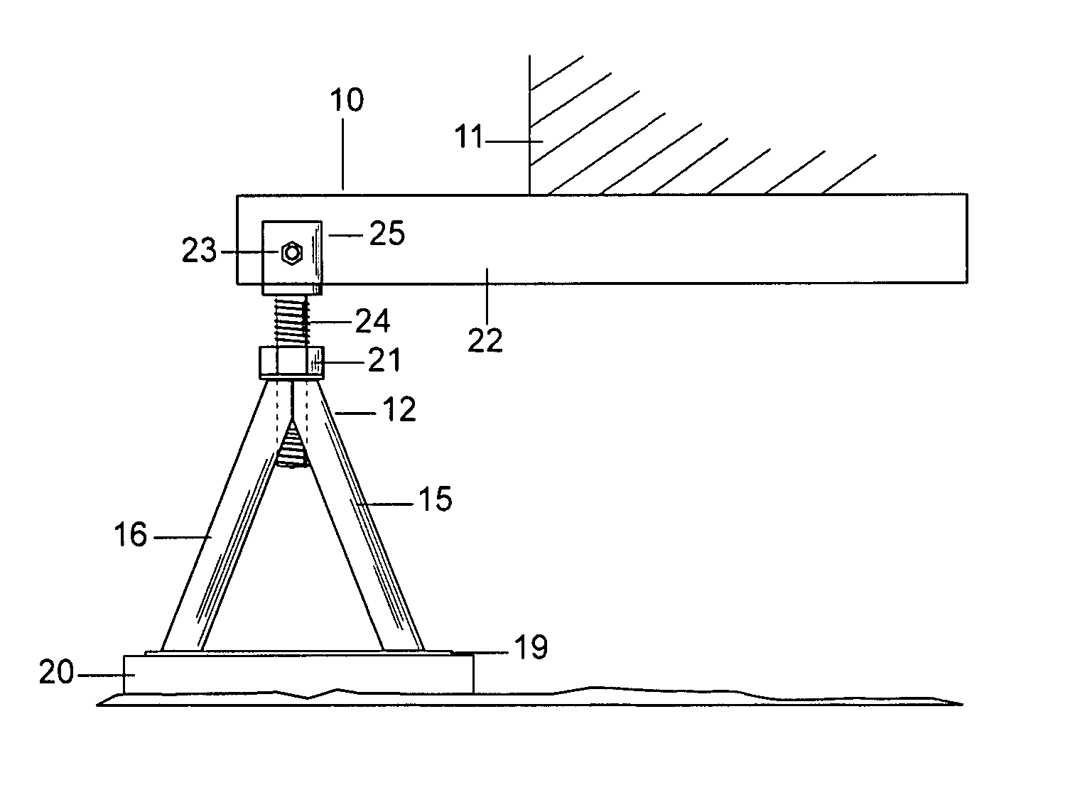
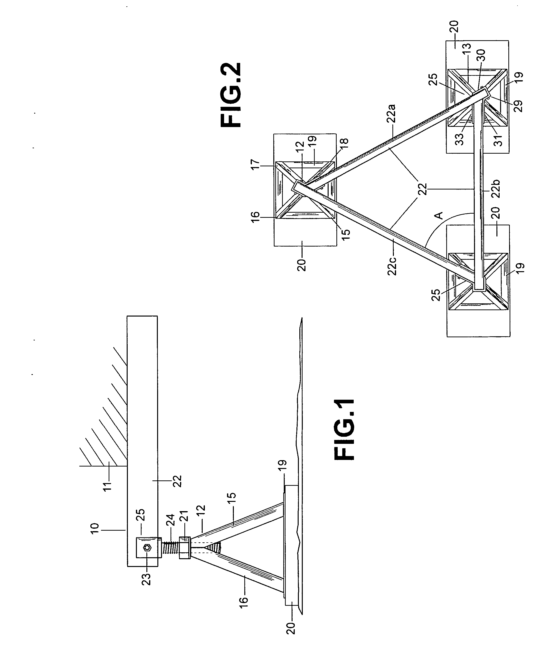
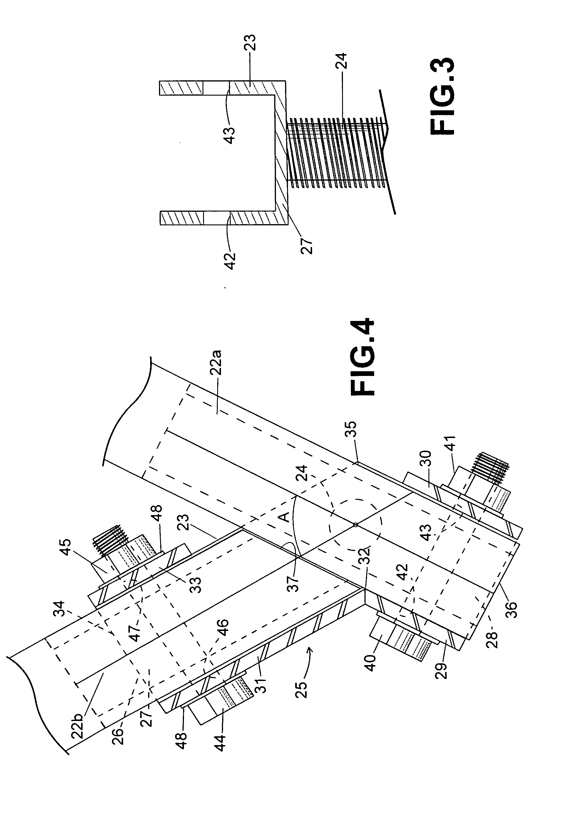
[0025] This improved method of forming a foundation uses a temporary prelevel coplanar support while installing a dynamic leveling permanent foundation. This improved method starts when a manufactured house arrives at the permanent site. The manufactured house has flooring assembly supported on its underside by horizontal parallel beams or joists that needs firmly grounded foundation support. The modular house may be a pair of elongated sections brought to the construction site by a truck. Preferably, the width of each module can fit on a single flatbed truck. The sections of the modular house are placed upon temporary supports by a crane and leveled. The buttress assemblies 210 arrive at the job site fully assembled and welded including the tubular stanchion 212, L-shaped bracket 211, vertical flange 214, base plate 217, anchor bolt head 218 or J shaped uplift bars, and steel tabs 219. Each of the sections of the modular house is joined to the others. Underneath the house the mate ...


PUM


Abstract

This improved method of forming a foundation uses a dynamic leveling foundation and method uses a prelevel coplanar support while installing permanent foundation. This improved method starts when a manufactured house arrives at the permanent site. The manufactured house has flooring assembly supported on its underside by horizontal parallel beams or joists that needs firmly grounded foundation support. The temporary support step provides a temporary level support for the manufactured house. When the temporary support is established, the house arrives from the factory. The preferred temporary support is a temporary tripod support system that may be installed under the sidewalls and the mate line. The tripod support system comprises multiple tripods each having a triangular transverse frame to support an extended undercarriage area. Each tripod makes at least two separate supporting abutments with its overlying perimeter joist or mate line joist which reduces total labor time.

Description

[0001] This application claims priority from and is a continuation in part of inventor Art Angelo's U.S. Ser. No. 11 / 317,349 Temporary Support System filed Dec. 23, 2005 and inventor Art Angelo's U.S. Ser. No. 11 / 226,962 Modular Buttress Foundation filed Sep. 15, 2005.BACKGROUND OF THE INVENTION [0002] A. Field of the Invention [0003] The present invention relates to a building foundation method for modular homes. [0004] B. Discussion of Related Art [0005] Traditional methods of making foundation in modular and manufactured homes have been inefficient and have damaged many homes causing loss to insurers and unnecessary environmental degradation because of demolition waste. If a modular house slips off its foundation, the house generally becomes uninhabitable and usually has to be demolished because of the foundation damage. This can cause a total loss of all time and effort and materials that were invested into the building. The old methods also waste time and material because redun...

Claims


Application Information

Patent Timeline
IPC IPC(8): E02D27/00
CPCE02D27/48
Inventor ANGELO, ART
Owner ANGELO ART
Why Eureka
Try Eureka