Pipeline leak detector

Active Publication Date: 2014-01-23
KING FAHD UNIVERSITY OF PETROLEUM AND MINERALS
View PDF5 Cites 5 Cited by
  • Summary
  • Abstract
  • Description
  • Claims
  • Application Information

AI Technical Summary

Benefits of technology

[0010]These and other features of the present invention will become readil

Problems solved by technology

Moreover, many liquids, such as petroleum products, are harmful when released into the general environment.
While water is not inherently toxic, it can also do great damage if a sufficient quantity is released into an area where it is not desired, e.g., flooding, soil erosion, softening of underlying soil and weakening of structural foundations, etc.
Even relatively small water leaks can result in damage over a prolonged period of time, and the economic loss resulting from the water loss can also be significant over a lengthy period of time, even when no envi

Method used


Image

  • Pipeline leak detector
  • Pipeline leak detector
  • Pipeline leak detector

Examples


Embodiment Construction

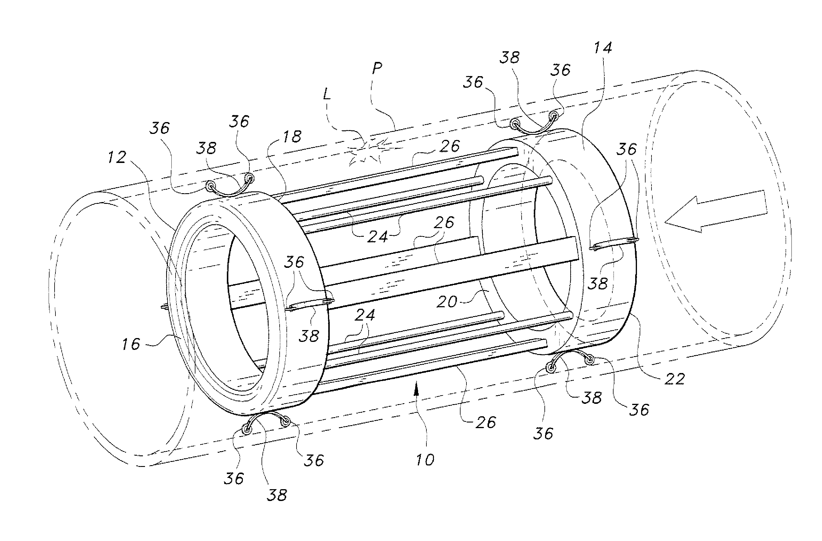
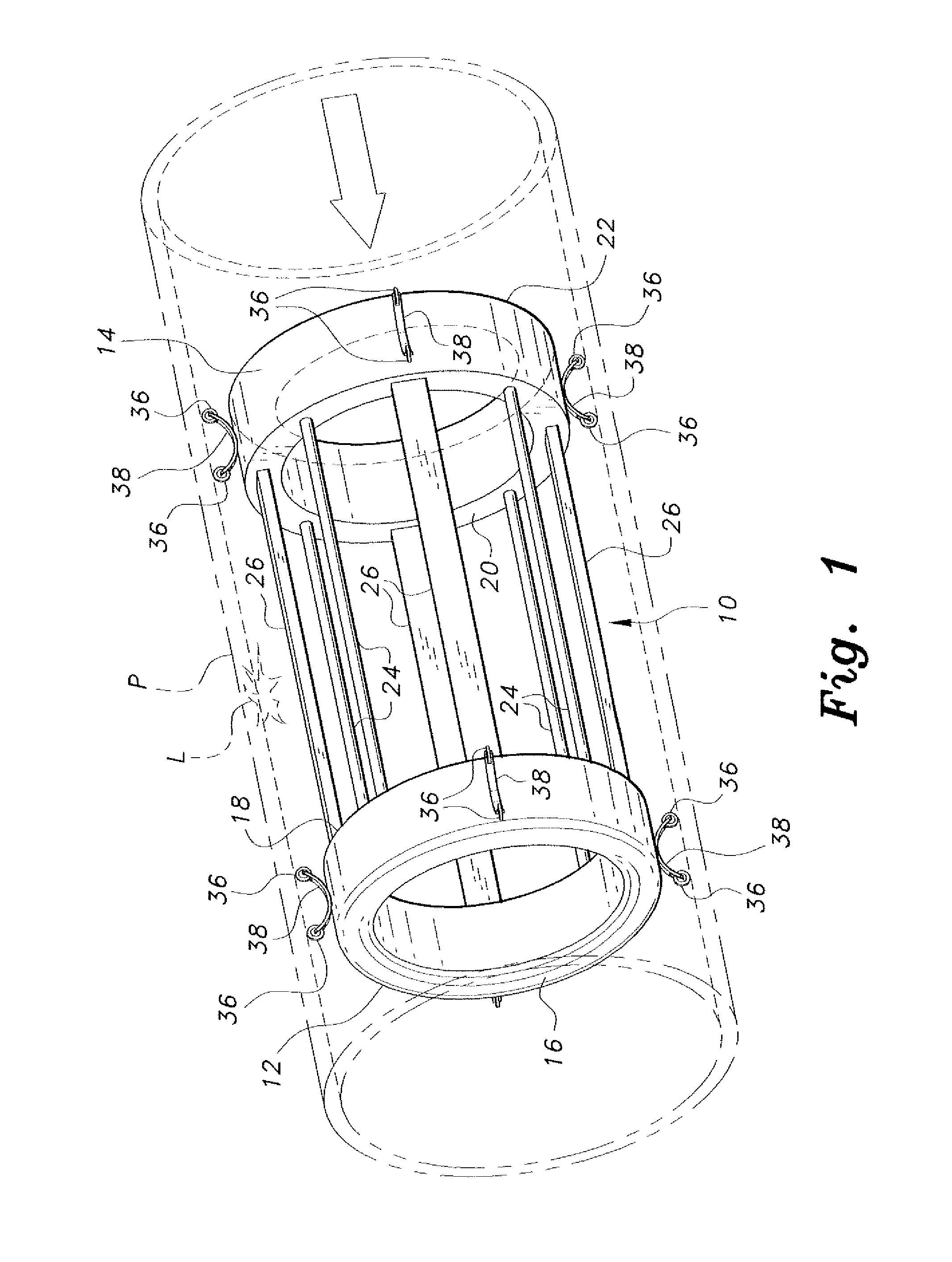
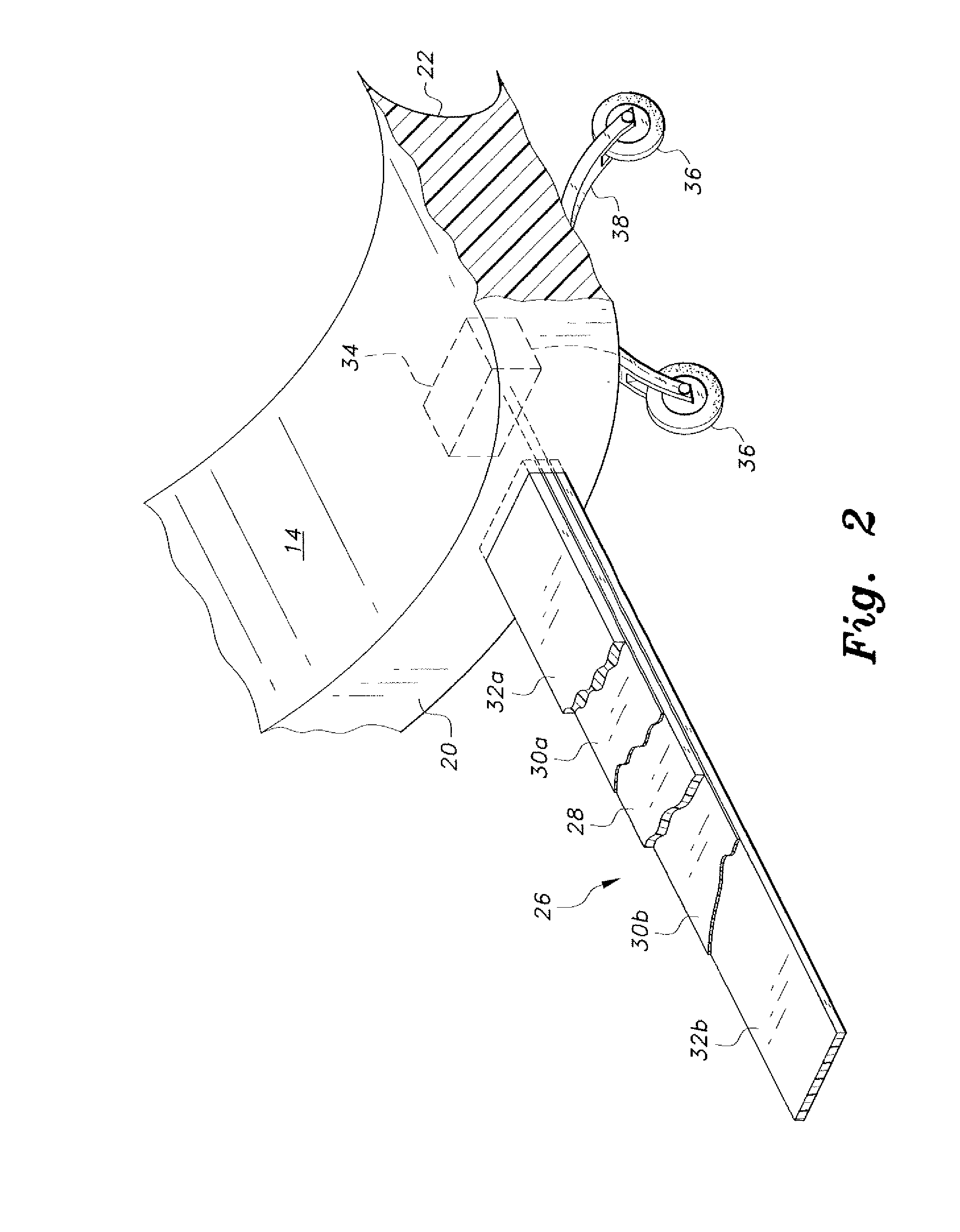
[0016]The pipeline leak detector is a passively mobile probe or device that travels through a liquid pipeline for detecting defects in the wall or joints of the pipeline. The device operates by means of a piezoelectric principle, wherein deflection of one or more piezoelectric elements due to a pressure differential in the pipe caused by leakage results in the generation of an electrical signal that is recorded and developed as the indication of a leak at the location of the pressure differential.

[0017]FIG. 1 provides an environmental perspective view of the pipeline leak detector 10 disposed within a pipeline P, the pipeline P being shown in broken lines. The pipeline leak detector 10 is a traveling probe having a leading or forward ring 12 and a trailing or rearward ring 14. The two toroidal rings have diameters slightly less than the inside diameter of the pipe P. The two rings 12 and 14 are designated as “leading” and “trailing,” because the first ring 12 will be at the forward ...


PUM


Abstract

The pipeline leak detector travels through a pipeline passively due to the flow of liquid through the pipeline. The device includes leading and trailing rings shaped to produce hydrodynamic resistance in order for the device to be carried through the pipeline. Wheels are provided about each ring. At least one wheel has an odometer to measure distance traveled through the pipe. The rings are joined by a plurality of axially oriented connecting rods. A plurality of sensing elements extend between the rings. Each sensing element has a thin laminate of a piezoelectric film sandwiched between two electrically conductive layers, and an electrically insulating coating on the outside of each conductive layer. One of the rings, e.g., the trailing ring, includes microelectronic circuitry for data acquisition and storage, e.g., estimates of the magnitude of any leakage encountered, the location of the leakage based upon the odometer travel, etc.

Description

BACKGROUND OF THE INVENTION[0001]1. Field of the Invention[0002]The present invention relates to devices and systems for detecting fluid leaks, and particularly to a pipeline leak detector that travels through a pipeline to detect leaks in the walls and / or joints of the pipeline.[0003]2. Description of the Related Art[0004]Pipelines for the conveyance of various liquids are often the most convenient means for transporting such liquids from one point to another. Obviously, there is some economic benefit or advantage in moving the liquids from one place to another, or there would be no point in spending the money to construct the pipeline in the first place. While many persons think of the conveyance of liquids, such as oil, as providing the greatest economic benefit, even less costly liquids, such as water, can provide significant economic benefit when they are transported from locations where they are readily available to locations where they are needed, e.g., major urban areas, agr...

Claims


Application Information

Patent Timeline
IPC IPC(8): G01M3/28
CPCG01M3/2823
Inventor HAWWA, MUHAMMAD A.AL-QAHTANI, HUSSAIN M.
Owner KING FAHD UNIVERSITY OF PETROLEUM AND MINERALS
Why Eureka
Try Eureka