Temperature compensating flanged joint for a teflon diaphragm valve

a temperature-compensating, diaphragm valve technology, applied in the direction of diaphragm valves, valve details, valve arrangements, etc., can solve the problems of leakage of process media through the joint between the diaphragm and the valve body, and achieve the effect of preventing radial movement of the teflon “gasket” section, constant sealing force and preventing radial movement of the teflon

Active Publication Date: 2014-01-23
ITT MFG ENTERPRISES LLC
View PDF10 Cites 6 Cited by
  • Summary
  • Abstract
  • Description
  • Claims
  • Application Information

AI Technical Summary

Benefits of technology

[0018]In effect, the present invention provides a substantially constant sealing force upon a plastic, typically Teflon, “gasket” section of the diaphragm by means of one or more metallic springs, regardless of variations in material dimensions caused by temperature fluctuation or material cold-flow (creep). The present invention also prevents radial movement of the Teflon “gasket” section by means of concentric fluctuations in the otherwise flat surface of the upper sealing member.
[0019]In operation, the concentric serrated edge on the live-loaded pressure ring penetrates the Teflon diaphragm minimizing cold-flow and preventing radial movement of the Teflon. The one or more Belleville washers or other mechanical spring(s) exert a relatively constant force, transmitted through the pressure ring, regardless of the small variations in thickness of the diaphragm that can be caused by temperature variation or material flow and age.
[0020]In addition to the concentric serrations, other geometry cross sections of the pressure ring can enhance the seal against the diaphragm face, including a wave, a radius, or flat, and do not have to penetrate the diaphragm to achieve the seal and radial clamp. The pressure ring may include a circular track to simplify manufacturing; however, other types or kinds of shapes, such as an oval, or more complex shapes, to the seal track are possible according to the present invention. Diaphragm materials other than Teflon may also be used with the present invention, including laminated composite materials such as Teflon laminated to EPDM with fabric. Other metal springs may be used in place of the Belleville washer to maintain the desired force through a lifetime of thermal cycles. The spring may be located as shown herein, deep in the bonnet, or close to the bonnet seal, or even adjacent to the diaphragm seal.

Problems solved by technology

Temperature variation and cold flow of plastic diaphragms, typically Teflon, has historically led to leaks of process media through the joint between the diaphragm and valve body.
An elastomeric member, typically included in the joint to provide compensation for these variations is inadequate to prevent leakage over long periods or multiple temperature cycles.

Method used


Image

  • Temperature compensating flanged joint for a teflon diaphragm valve
  • Temperature compensating flanged joint for a teflon diaphragm valve
  • Temperature compensating flanged joint for a teflon diaphragm valve

Examples


Embodiment Construction

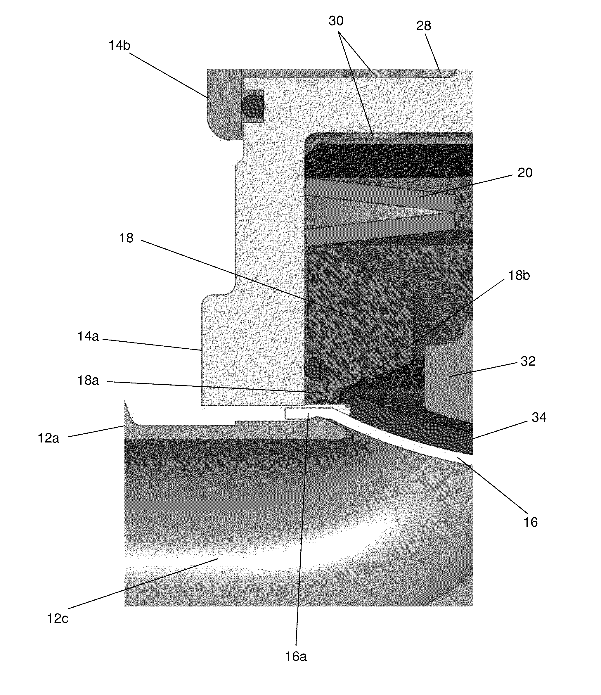
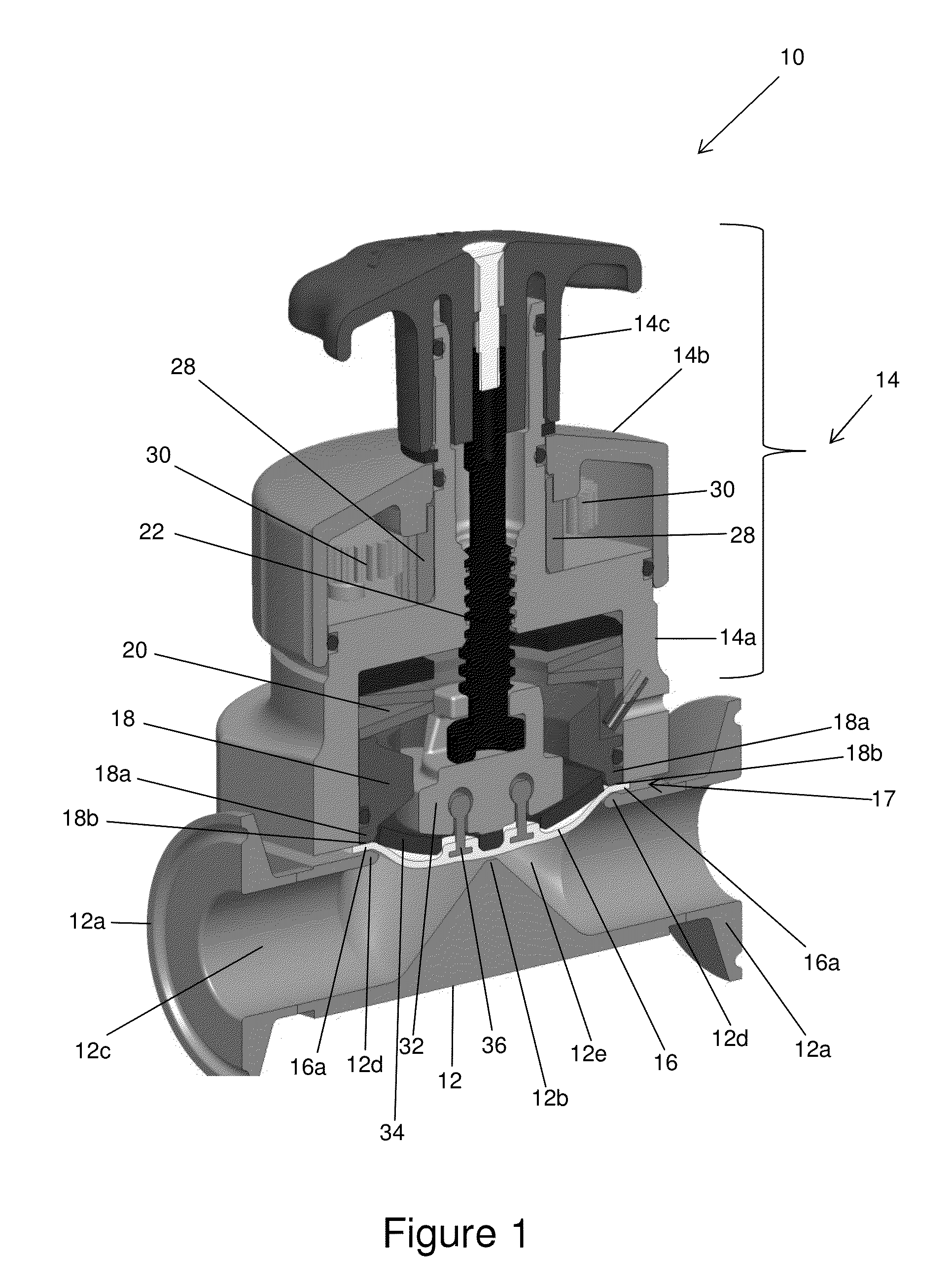
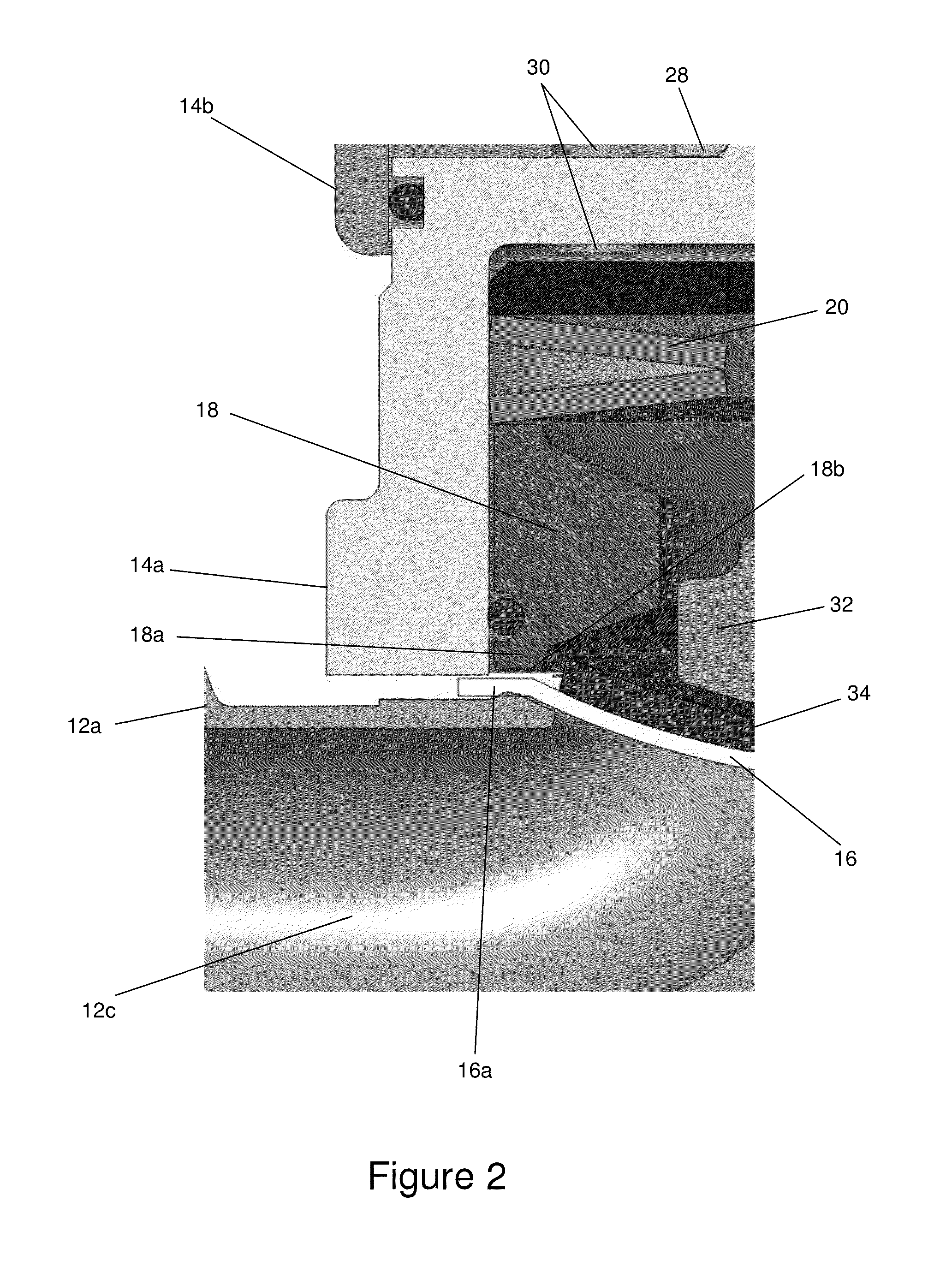
[0025]FIGS. 1-2 shows apparatus, in the form of a diaphragm valve, generally indicated as 10 according to some embodiments of the present invention, having a valve body 12 and a bonnet assembly 14. The bonnet assembly 14 is configured with a diaphragm 16, a pressure ring 18 and at least one elastomeric member 20. As a person skilled in the art would appreciate, the bonnet assembly 14 is also configured with other elements that do not form part of the underlying invention set forth herein, are described in detail herein, but that are described in corresponding patent application Ser. No. ______ (911-002.049-1 / / FEV1201US), which is hereby incorporated by reference in its entirety.

[0026]The valve body 12 may include input / output ports 12a, a weir portion 12b, a fluid flow channel 12c, a circumferential flange 12d configured around, and forming an opening generally indicated by an arrow labeled 12e. The weir portion 12b is configured to control a flow of fluid through the fluid flow cha...


PUM


Abstract

Apparatus, including a diaphragm valve, is provided featuring a valve body, a diaphragm, a pressure ring, and at least one elastomeric member. The valve body may include a circumferential flange. The diaphragm may include a circumferential gasket portion configured to be seated on the circumferential flange so as to form a joint between the valve body and the diaphragm. The pressure ring may include concentric fluctuations, and may be configured to apply a sealing force against the joint so that the concentric fluctuations prevent radial movement of the circumferential gasket portion and the circumferential flange. The elastomeric member may be configured to respond to a compressive force and provide a substantially constant sealing force, transmitted through the pressure ring, regardless of small variations in the thickness or material dimensions of the circumferential gasket portion caused by temperature fluctuation or material flow and age.

Description

BACKGROUND OF THE INVENTION[0001]1. Field of the Invention[0002]The present invention relates to a diaphragm valve; and more particularly relates to a weir-type diaphragm valve.[0003]2. Brief Description of Related Art[0004]Temperature variation and cold flow of plastic diaphragms, typically Teflon, has historically led to leaks of process media through the joint between the diaphragm and valve body. An elastomeric member, typically included in the joint to provide compensation for these variations is inadequate to prevent leakage over long periods or multiple temperature cycles.[0005]Low friction coefficient of Teflon material allows the diaphragm to slide between the mating flanges, radially, when the valve is cycled and thus carry process media into the crevice between the plastic diaphragm and the valve body flange.SUMMARY OF THE INVENTION[0006]According to some embodiments, the present invention may take the form of apparatus, including a diaphragm valve, that includes a valve ...

Claims


Application Information

Patent Timeline
Patent Type & Authority Applications(United States)
IPC IPC(8): F16K5/14
CPCF16K5/14F16K7/126
Inventor MATALON, LOUIS E.BUTLER, RONALD G.
Owner ITT MFG ENTERPRISES LLC
Why Eureka
Try Eureka