Rotor and rotary electric machine using the same

a technology of rotary electric machines and rotors, applied in the field of rotors, can solve the problems of increasing costs, and achieve the effects of reducing machine performance degradation, easy setting of magnetic resistance, and convenient fabrication

Active Publication Date: 2014-01-23
DAIKIN IND LTD
View PDF5 Cites 21 Cited by
  • Summary
  • Abstract
  • Description
  • Claims
  • Application Information

AI Technical Summary

Benefits of technology

[0036]In the first aspect, the intensity of the opposing magnetic field applied on the permanent magnets (220) can be reduced, and a reluctance torque can be produced by the first rotor core (240). Thus, a rotary electric machine including a rotor having a rotor core equipped with magnets can be provided with measures against demagnetization while reducing performance degradation of the machine.
[0037]In the second aspect, the magnetic resistance can be determined depending on a radial width (Wg1) of the gaps (241), thereby easily setting the magnetic resistance.
[0038]In the fourth aspect, a large part of an opposing magnetic field applied on the rotor (200) travels toward both axial ends, and thus, measures against demagnetization can be obtained at both ends of the permanent magnets (220). In addition, since the magnet-housing slots (211) are covered with the first rotor core (240), a cover for preventing detachment of the permanent magnets (220), for example, can be omitted.
[0039]In the fifth aspect, since a large part of the opposing magnetic field applied on the rotor (200) travels toward an axial center, measures against demagnetization can be obtained at the axial center of each of the permanent magnets (220). In this configuration, the permanent magnets (220) can be inserted from both axial ends of the rotor (200). Thus, the rotor (200) can be easily fabricated.
[0040]In the seventh aspect, a short circuit of the magnetic flux can be prevented, thereby stably operating the rotary electric machine.

Problems solved by technology

However, these measures disadvantageously lead to an increase in cost.

Method used


Image

  • Rotor and rotary electric machine using the same
  • Rotor and rotary electric machine using the same
  • Rotor and rotary electric machine using the same

Examples


first embodiment

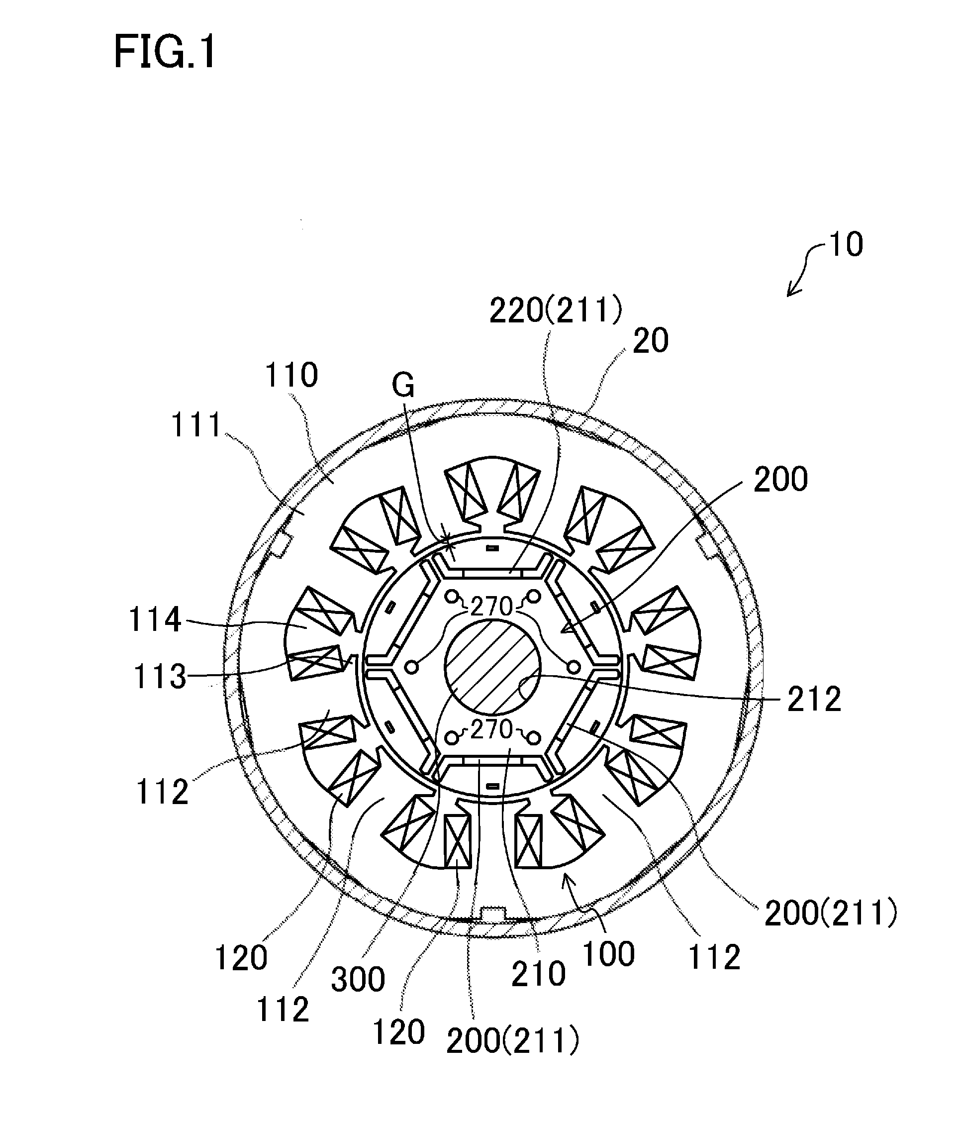
[0062]FIG. 1 is a transverse sectional view illustrating a motor (10) according to a first embodiment of the present invention. The motor (10) is used for, for example, an electric compressor (not shown) of an air conditioner.

[0063]10)>

[0064]As illustrated in FIG. 1, the motor (10) includes a stator (100), a rotor (200), and a driving shaft (300), and is housed in a casing (20) of the electric compressor. In the following description, the “axial direction” or “axial” refers to the direction along the axis of the driving shaft (300), and the “radial direction” or “radial” refers to the direction orthogonal to the axis. The outer peripheral side refers to a distal side relative to the axis, whereas the inner peripheral side is a proximal side relative to the axis.

[0065]100)>

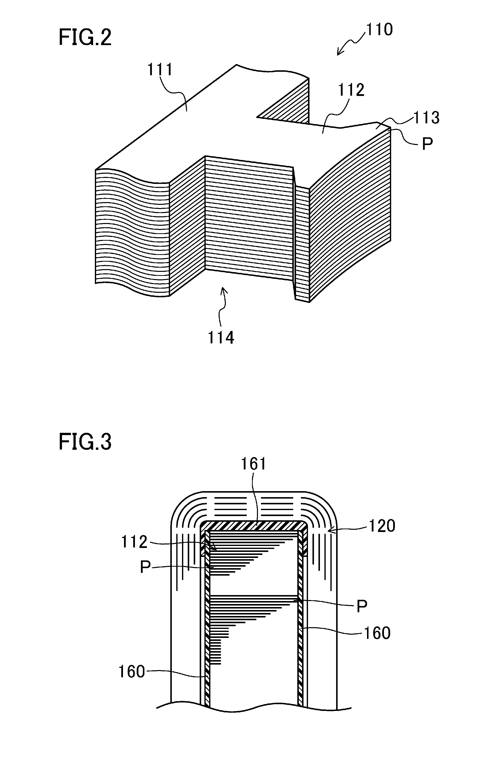
[0066]As illustrated in FIG. 1, the stator (100) a cylindrical stator core (110) and a coil (120).

[0067]The stator core (110) is a multilayer core obtained by forming a plate through punching of a flat rolled magne...

second embodiment

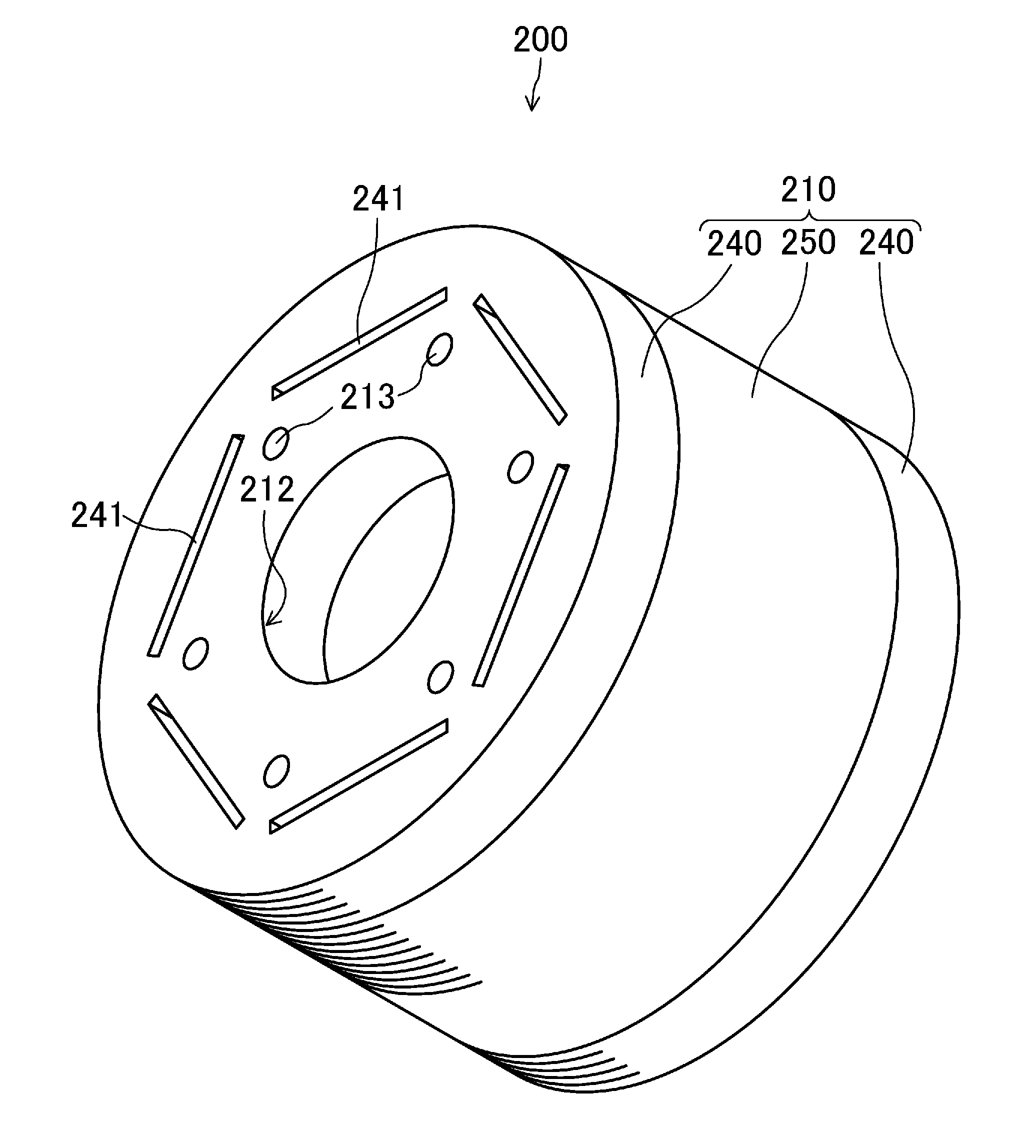
[0094]FIG. 10 is a sectional view illustrating a rotor (200) according to a second embodiment of the present invention. The rotor (200) of this embodiment includes a first rotor core (240) and a second rotor core (250). In this embodiment, the height (H1) (i.e., an axial dimension) of the first rotor core (240) is also smaller than the height (H2) of the second rotor core (250). The first rotor core (240) is in contact with the second rotor core (250) at their axial ends.

[0095]In this configuration of this embodiment, even upon an application of an opposing magnetic field on the rotor (200), a large part of the magnetic flux travels toward a magnetic core portion (240a) near the first rotor core (240). Thus, in this embodiment, measures against demagnetization can be provided in permanent magnets (220) near the first rotor core (240). In the second rotor core (250), the permanent magnets (220) can be easily inserted in magnet-housing slots (211) from an axial end of the second rotor...

third embodiment

[0096]FIG. 11 is a sectional view illustrating a rotor (200) according to a third embodiment of the present invention. The rotor (200) of this embodiment includes a first rotor core (240) and two second rotor cores (250). The first rotor core (240) is sandwiched between the second rotor cores (250) in the axial direction. In this embodiment, the height (H1) (i.e., an axial dimension) of the first rotor core (240) is also smaller than the height (H2) of the second rotor cores (250).

[0097]In this configuration of the third embodiment, even upon an application of an opposing magnetic field on the rotor (200), a large part of the magnetic flux travels toward a magnetic core portion (240a) near the first rotor core (240). Thus, measures against demagnetization of permanent magnets (220) can be provided near the axial center of rotor (200) on which a relatively strong opposing magnetic field is likely to be applied.

[0098]In addition, the permanent magnets (220) can be inserted from both a...


PUM


Abstract

A first rotor core including a plurality of gaps penetrating through the first rotor core along an axial direction is provided. A second rotor core being in contact with an axial end of the first rotor core and having a plurality of magnet-housing slots facing the gaps is also provided. The gaps have a magnetic resistance lower than that of the magnet-housing slots.

Description

TECHNICAL FIELD[0001]The present invention relates to rotors including rotor cores equipped with magnets and rotary electric machines using such rotors.BACKGROUND ART[0002]Rotary electric machines, e.g., synchronous reluctance motors (SynRMs) employing auxiliary magnets, and interior permanent magnet motors (IPMs) include rotor cores equipped with magnets. Such a rotary electric machine occasionally shows reduction of magnetic force (i.e., demagnetization) of permanent magnets of the rotor core due to an application of a large opposing magnetic field caused for some reasons. To cope with this demagnetization, an increase in thickness of magnets, for example, may be effective. However, these measures disadvantageously lead to an increase in cost.[0003]Another example of measures against demagnetization is devising the path of a magnetic flux (see, for example, Patent Document 1). In this example, a magnetic member is disposed on the surface of a permanent magnet. An end ring of a mag...

Claims


Application Information

Patent Timeline
Patent Type & Authority Applications(United States)
IPC IPC(8): H02K1/27
CPCH02K1/276H02K1/246H02K1/2766H02K2213/03
Inventor KONDOU, TOSHINARIYASUDA, YOSHIKIYAMAGIWA, AKIO
Owner DAIKIN IND LTD
Why Eureka
Try Eureka