Receiver and Reception Processing Method

a processing method and reception technology, applied in the field of reception processing methods, can solve the problems of reducing affecting the performance of the receiving process, and affecting the performance of the limit process, so as to reduce the degradation of performance in the multi-path environment and improve the performance in one-path environmen

Inactive Publication Date: 2009-01-08
FUJITSU LTD
View PDF7 Cites 4 Cited by
  • Summary
  • Abstract
  • Description
  • Claims
  • Application Information

AI Technical Summary

Benefits of technology

[0018]It is an object of the present invention to improve performance in one-path environment while reducing performance degradation in multi-path environment.
[0031]The above-described technique can improve performance in one-path environment while reducing performance degradation in multi-path environment.

Problems solved by technology

Therefore, in an environment in which the radio propagation path is one-path or near one-path (hereinafter collectively referred to as “one-path environment”), a transmission format that allows fast transmission is used, but if such a format is used, the performance may be significantly degraded by the mixing of small noise.
The RAKE receiver improves receiving performance by combining multiple delayed waves, but in one-path environment, it often causes false detection of delayed waves, and as a result, it combines noise components, which may degrade the receiving performance.
Furthermore, the limit process does not work well since there is a certain limit to the improvement in accuracy of path power estimation.
This may also be a cause of the performance degradation.
As seen from the curves 100, 200, and 300, in one-path environment, higher limit threshold provides better performance, but in multi-path environment such as PB3 (moving environment at 3 km / h) and VA120 (moving environment at 120 km / h), higher limit threshold provides degraded performance because of poor accuracy of the limit process performing determination.
This means that there is a trade-off between the limit threshold and the performance.

Method used


Image

  • Receiver and Reception Processing Method
  • Receiver and Reception Processing Method
  • Receiver and Reception Processing Method

Examples


first embodiment

[A] A First Embodiment

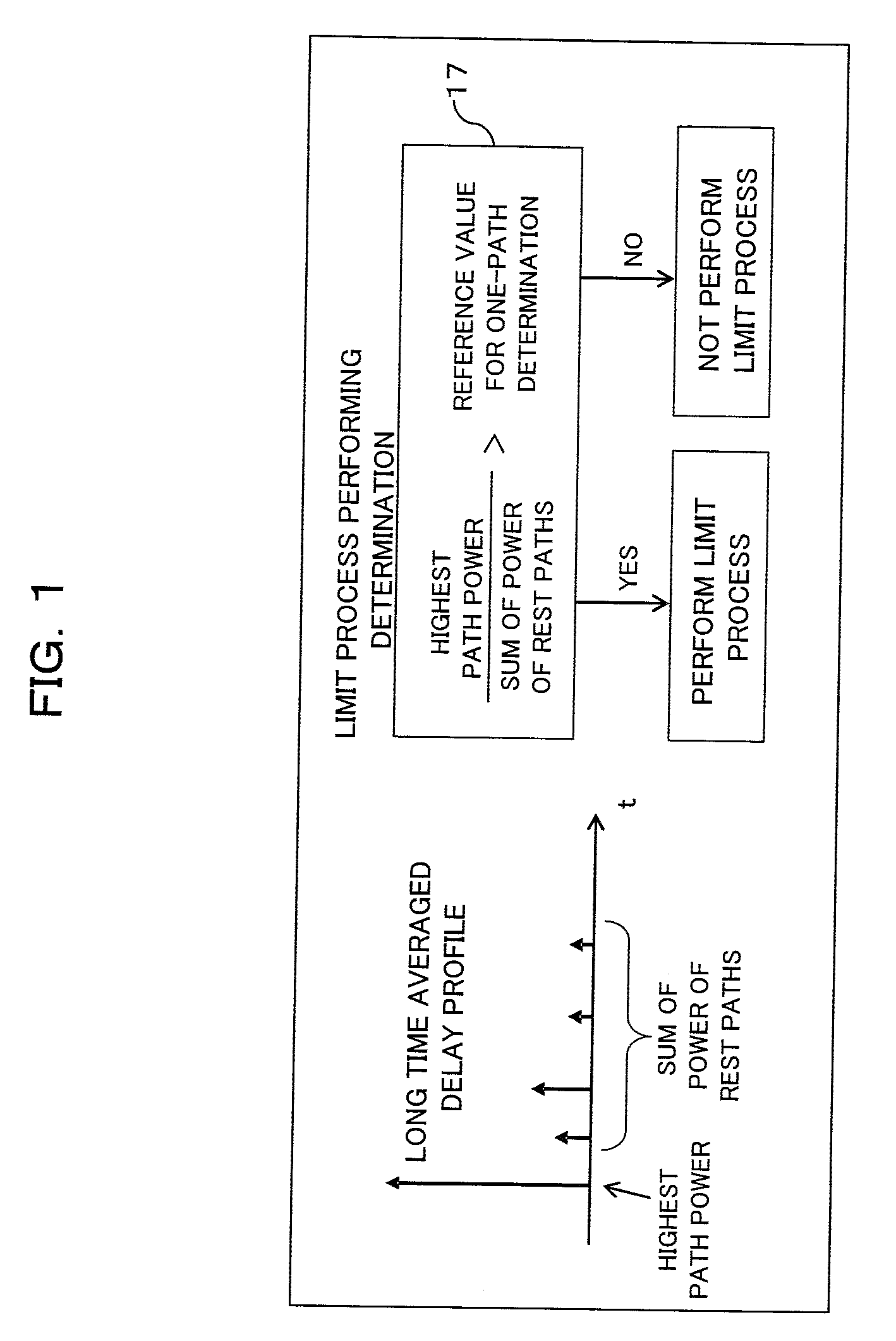
[0047]The above mentioned problem can be solved by selectively performing a limit process depending on a given propagation environment. For example, instead of being always performed, the limit process is performed when a given propagation environment is determined to be one-path environment after the long-time measurement of the environment. This can improve performance in one-path environment while reducing performance degradation in multi-path environment. Note that an overflowing path from the physically combinable number of paths (N) (for example, the N+1-th or later path when arranged in the order of decreasing correlation) is excluded from the combining (this exclusion is different process from the limit process).

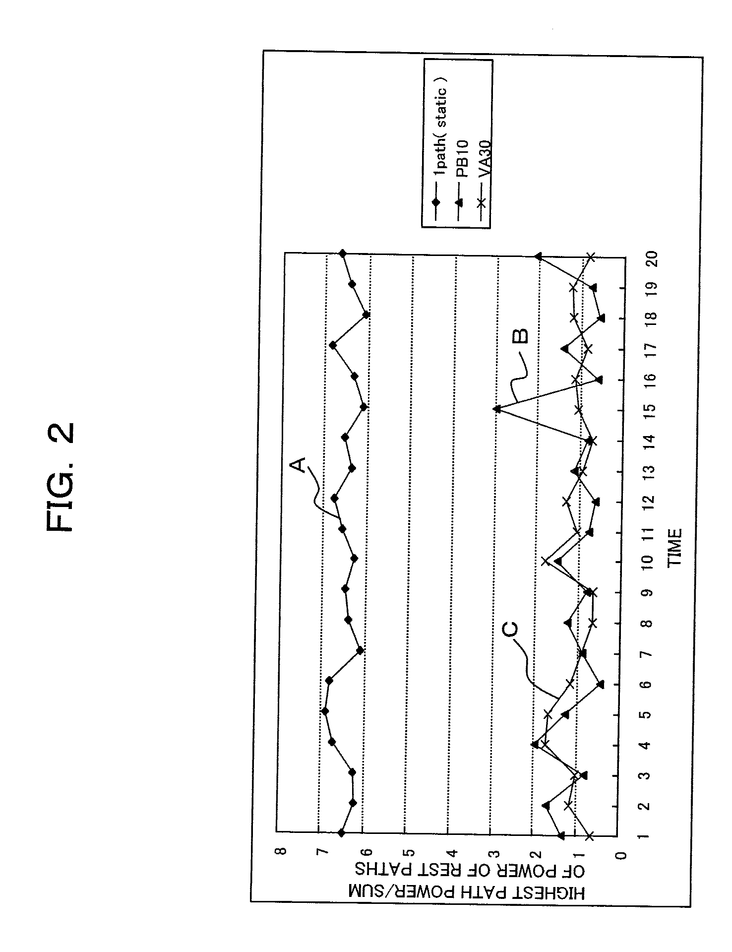
[0048]Whether a given environment is one-path or not can be determined based on the ratio between the highest path power (power of path whose power is the highest) and the sum of power of the rest of paths in the delay profile measured for a suf...

second embodiment

[B] A Second Embodiment

[0065]FIGS. 5 to 7 illustrate the limit process performing determination process in a CDMA receiver in accordance with a second embodiment. This process is a modification of the process of the limit process performing determination by the limit process performing determination part 17 shown in FIGS. 1 and 3, and uses an equalizer.

[0066]As shown in FIG. 5, the limit process is performed when the difference between the gain of the equalizer of the CDMA receiver and the gain of the RAKE receiver is lower than a predetermined reference value (for example, 0).

[0067]FIG. 6 shows an example of configuration for calculating the difference of the gains. In this configuration, a known signal (pilot signal) is input to an equalizer 18 and a RAKE receiver 19. S / N calculators 20 and 21 calculate (estimate) the S / N ratios of the output from the equalizer 18 and RAKE receiver 19, respectively. An S / N difference calculator 22 calculates the difference between the S / N ratios. ...

third embodiment

[C] A Third Embodiment

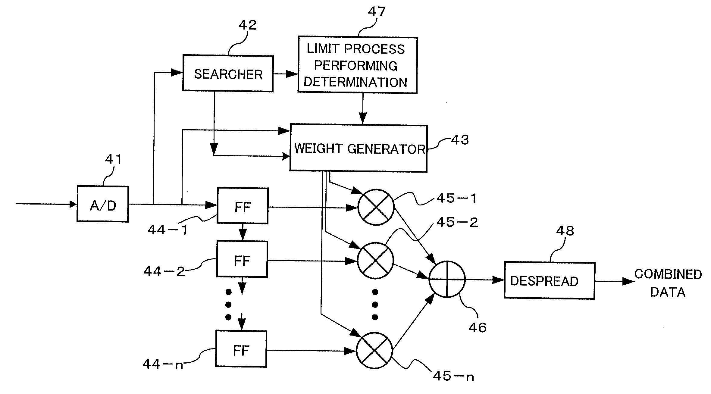
[0078]FIG. 9 is a block diagram of a equalizer in a CDMA receiver in accordance with a third embodiment. The equalizer shown in FIG. 9 is applicable to a receiver system of a wireless terminal such as mobile phone, and includes, for example, an A / D converter 41, a searcher 42, a weighting factor generator 43, delay circuits (FF) 44-1 to 44-n (n is an integer greater than 1), multipliers (45-1 to 45-n), an adder 46, a limit process performing determination part 47, and a despreader 48.

[0079]As seen from FIG. 9, this equalizer has generally the similar configuration as the RAKE receiver shown in FIG. 3, and is configured to be operable as equalizer and RAKE receiver for a received signal before being despread.

[0080]The A / D converter 41 converts a signal (analog baseband signal) that is received by a receiving antenna (not shown) and subjected to necessary radio reception processes including low-noise amplification, frequency conversion (down conversion), automati...


PUM


Abstract

A receiver including: a delay profile generating unit to generate a delay profile from a received signal; combining unit operable to combine multiple received signals with different timings; a determining unit to determine whether or not the propagation environment of the received signals is multi-path, based on the delay profile; and a control unit operable to exclude any signal with timing whose power is equal to or lower than a predetermined threshold in the delay profile from the combining, upon the determination not being multi-path.

Description

CROSS REFERENCE TO RELATED APPLICATION(S)[0001]This application is based on and hereby claims priority to Japanese Application No. 2007-174184 filed on Jul. 2, 2007 in Japan, the contents of which are hereby incorporated by reference.BACKGROUND OF THE INVENTION[0002](1) Field of the Invention[0003]The present invention relates to receivers and reception processing methods. The present invention may be used in a receiver system in a CDMA wireless terminal, for example.[0004](2) Description of the Related Art[0005]In recent years, many studies on high-speed and high capacity mobile communication method have been done. As a part of this trend, developments of high-speed wireless communication method using CDMA scheme, including HSDPA (High Speed Downlink Packet Access), have been increasing.[0006]HSDPA provides near-highest transmission speed in a given radio propagation environment by adaptively changing the transmission format depending on the given environment.[0007]Therefore, in an...

Claims


Application Information

Patent Timeline
Patent Type & Authority Applications(United States)
IPC IPC(8): H04B1/707H04L27/01H04L27/00H04B1/10H04J13/00
CPCH04B1/7113H04B1/7115H04B2201/70707H04B1/712H04B1/7117
Inventor HASEGAWA, TSUYOSHI
Owner FUJITSU LTD
Why Eureka
Try Eureka