
Apparatus and Method for Disabling the Operation of High Power Devices

a technology for disabling and operating devices, applied in the direction of electronic commutators, motor/generator/converter stoppers, dynamo-electric converter control, etc., can solve the problem of only operating load

Inactive Publication Date: 2014-01-23
ROCKWELL AUTOMATION TECH
View PDF9 Cites 2 Cited by
  • Summary
  • Abstract
  • Description
  • Claims
  • Application Information

AI Technical Summary

Benefits of technology

This solution provides a reliable, efficient, and cost-effective method to disable high power devices, ensuring safety without the drawbacks of traditional high power contactors, and meets safety standards by preventing unintended operation.

Problems solved by technology

Indeed, in some of these circumstances, for example, the load is only capable of operating if it receives carefully controlled power levels that vary in time in addition to being of high magnitude.

Method used


Image

  • Apparatus and Method for Disabling the Operation of High Power Devices
  • Apparatus and Method for Disabling the Operation of High Power Devices
  • Apparatus and Method for Disabling the Operation of High Power Devices

Examples


Embodiment Construction

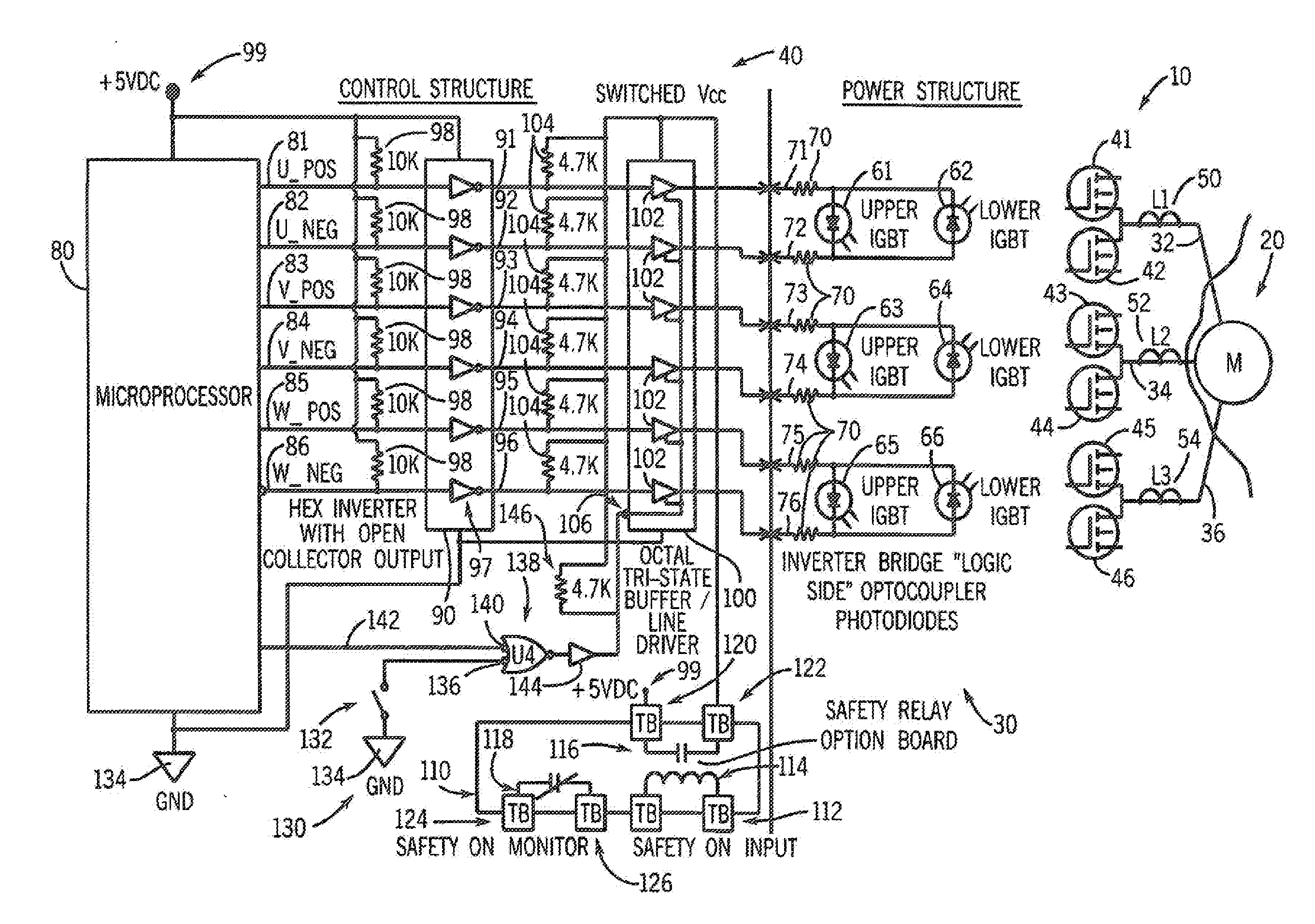
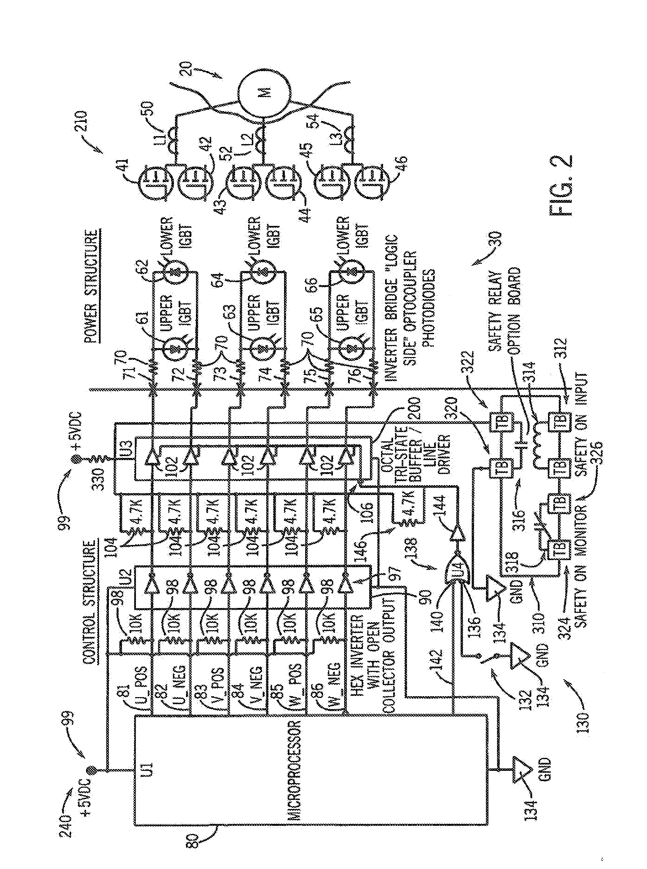
[0018]Referring to FIG. 1, an exemplary drive circuit 10 for providing high levels of power to a motor 20 is shown. The drive circuit 10 includes a high power drive section 30 and a low power logic section 40. The high power drive section 30 also can be termed a power structure, while the low power logic section 40 can be termed a control structure.

[0019]As shown, first, second and third phases of power 32, 34 and 36, respectively, are delivered to the motor 20 from six power transistor devices 41-46. In the present embodiment, each of the power transistor devices 41-46 is an insulated gate bipolar transistor (IGBT) although, in alternate embodiments, other types of power transistor devices (or other, non-transistor power delivery devices) can be used. Each of the first, second and third phases 32, 34 and 36 receives voltage from a respective pair of the power transistor devices 41-42, 43-44, and 45-46, respectively. Current flows toward or away from the motor 20 in each phase 32, 3...


PUM


Abstract

A drive circuit for delivering high-level power to a load, and method of stopping a high power load from operating, are disclosed. The drive circuit includes a high power circuit capable of being coupled to the load and delivering the high level power thereto, and a to power circuit that controls the high power circuit. The low power circuit includes a first circuit portion that provides at least one control signal that is at least indirectly communicated to the high power circuit and that controls the delivering of the high level power by the high power circuit, and a second circuit portions coupled to the first circuit portion. The second circuit portion is capable of disabling the first circuit portion so that the at least one control signal avoids taking on values that would result in the high power circuit delivering the high level power to the load.

Description

CROSS-REFERENCE TO RELATED APPLICATIONS[0001]This application is a divisional of U.S. patent application Ser. No. 10 / 730,430, filed Dec. 8, 2003, which is hereby incorporated by reference for all purposes.FIELD OF THE INVENTION[0002]The present invention relates to drive circuits that are used to control the delivery of high power levels to high power loads such a motors and more particularly, to the disabling of the power delivered by of such drive circuits so that the loads are no longer driven.BACKGROUND OF THE INVENTION[0003]High power devices are commonly employed in a variety of environments including, for example, industrial facilities and construction environments. High power devices generally include a variety of different devices including, for example, motors and heating devices. Although the operation of such de ices under normal conditions does not pose undue risk, there are circumstances in which such devices must be reliably disabled so as not to pose risks to human b...

Claims


Application Information

Patent Timeline
Patent Type & Authority Applications(United States)
IPC IPC(8): H02P6/14H02M1/00H02M1/092H02M1/32H02M7/5387H02P29/02
CPCH02P6/14H02M1/092H02M1/32H02M7/53875H02P29/02
Inventor FULLINGTON, DAVID G.SLADKY, RAYMOND G.STEWART, DANIEL L.GASPERI, MICHAEL L.MILES, SCOTT P.
Owner ROCKWELL AUTOMATION TECH
Features
  • Generate Ideas
  • Intellectual Property
  • Life Sciences
  • Materials
  • Tech Scout
  • Unparalleled Data Quality
  • Higher Quality Content
  • 60% Fewer Hallucinations
Learn More