Simplified spring load mechanism for delivering shaft force of a surgical instrument

a surgical instrument and spring load technology, applied in the field of surgical instruments, can solve the problems of preventing energy from being transferred through the tissue, tissue may have a tendency to move before an adequate seal, and achieve the effect of limiting further longitudinal motion

Active Publication Date: 2014-01-23
TYCO HEALTHCARE GRP LP
View PDF25 Cites 51 Cited by
  • Summary
  • Abstract
  • Description
  • Claims
  • Application Information

AI Technical Summary

Benefits of technology

[0032]According to another aspect of the present disclosure, a connection mechanism for a surgical instrument is provided. The connection mechanism includes an inner shaft member that is configured to extend at least partially through an elongated shaft member of a surgical instrument and that defines proximal and distal ends. The inner shaft member is selectively movable in a longitudinal direction with respect to the elongated shaft member. The inner shaft member includes at least one aperture defined therein and that extends partially along the longitudinal direction of the inner shaft memb

Problems solved by technology

If an adequate gap distance is not maintained, there is a possibility that the opposed electrodes will contact one another, which may cause a short circuit and prevent energy from being transferred through the tissue.
Also, if too low a force is applied the tissue may have a tendency t

Method used


Image

  • Simplified spring load mechanism for delivering shaft force of a surgical instrument
  • Simplified spring load mechanism for delivering shaft force of a surgical instrument
  • Simplified spring load mechanism for delivering shaft force of a surgical instrument

Examples


Embodiment Construction

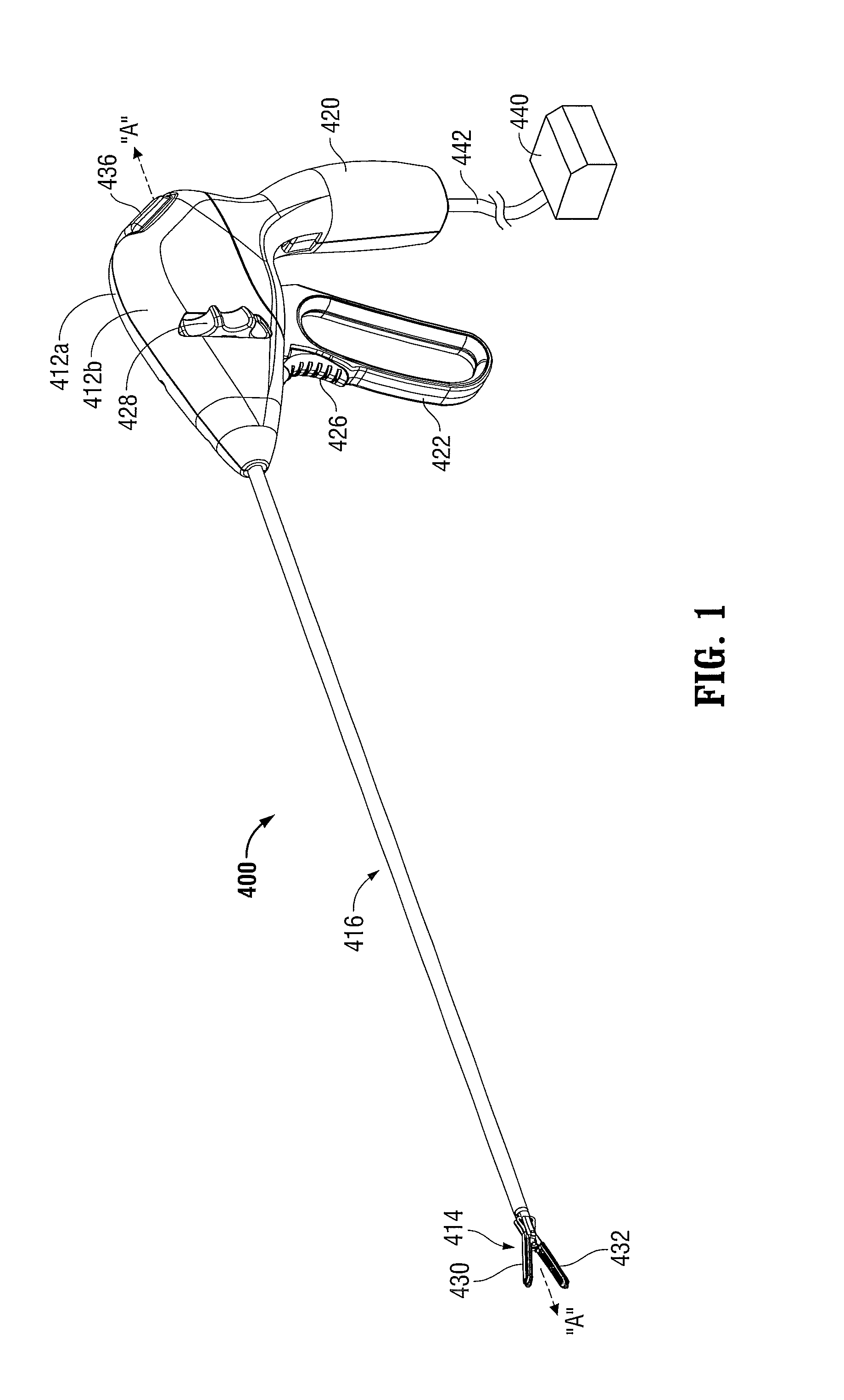
[0092]Referring initially to FIG. 1, an embodiment of an electrosurgical forceps 400 generally includes a housing 412 that supports various actuators thereon for remotely controlling an end effector 414 through an elongated shaft 416. Although this configuration is typically associated with instruments for use in laparoscopic or endoscopic surgical procedures, various aspects of the present disclosure may be practiced with traditional open instruments and in connection with endoluminal procedures as well.

[0093]The housing 412 is constructed of a left housing half 412a and a right housing half 412b. The left and right designation of the housing halves 412a, 412b refer to the respective directions as perceived by an operator using the forceps 400. The housing halves 412a, 412b may be constructed of sturdy plastic, and may be joined to one another by adhesives, ultrasonic welding or other suitable assembly methods.

[0094]To mechanically control the end effector 414, the housing 412 supp...


PUM

PropertyMeasurementUnit
Forceaaaaaaaaaa
Densityaaaaaaaaaa

Abstract

A connection mechanism and manufacturing method for a surgical instrument includes an inner shaft member that extends at least partially through an elongated shaft member of the instrument and defines proximal and distal ends and is selectively movable in a longitudinal direction with respect to the elongated shaft member and includes at least one aperture that extends partially along the longitudinal direction and disposed distally from the proximal end. The inner shaft member enables a drive collar member to slide on the inner shaft member and reciprocate along the longitudinal direction. A drive collar stop member slides on the inner shaft member and moves along the longitudinal direction. The drive collar stop member then moves in a direction relative to the longitudinal axis to engage the aperture and limit further longitudinal motion of the drive collar member. An inner shaft stop member limits movement of the inner shaft.

Description

CROSS-REFERENCE TO RELATED APPLICATIONS[0001]This application is a continuation-in-part of U.S. patent application Ser. No. 13 / 461,335, entitled “SURGICAL INSTRUMENT WITH STAMPED DOUBLE-FLAG JAWS” by James D. Allen, IV, et al., filed on May 1, 2012.BACKGROUND[0002]1. Technical Field[0003]The present disclosure relates generally to the field of surgical instruments. In particular, the disclosure relates to an endoscopic electrosurgical forceps that is economical to manufacture and is capable of sealing and cutting relatively large tissue structures. The present disclosure relates also to connection mechanisms to actuate the jaw members of a surgical instrument.[0004]2. Background of Related Art[0005]Instruments such as electrosurgical forceps are commonly used in open and endoscopic surgical procedures to coagulate, cauterize and seal tissue. Such forceps typically include a pair of jaws that can be controlled by a surgeon to grasp targeted tissue, such as, e.g., a blood vessel. The ...

Claims


Application Information

Patent Timeline
IPC IPC(8): A61B18/14
CPCA61B18/1445A61B18/1482A61B2017/0046A61B2017/00477A61B2017/00526A61B2017/2902A61B2017/292A61B2017/2929A61B2017/293A61B2017/2936A61B2017/2946A61B2018/00601A61B2018/00607A61B2018/0063A61B2018/00952A61B2018/1455A61B90/03A61B2090/031A61B2090/033A61B2090/034Y10T29/49002Y10T29/49826Y10T403/32549A61B17/2812A61B2017/00367A61B2018/00619
Inventor SIMS, GRANT T.LYONS, MICHAEL B.
Owner TYCO HEALTHCARE GRP LP
Why Eureka
Try Eureka