Sensor for measuring high humidity conditions and/or condensation

a technology of humidity sensor and sensor, which is applied in the field of humidity sensor, can solve problems such as visibility problems, corrosion of metallic surfaces, and condensation such as the formation of “fogging” or actual water droplets on the surfa

Inactive Publication Date: 2014-01-30
SILICON LAB INC
View PDF18 Cites 21 Cited by
  • Summary
  • Abstract
  • Description
  • Claims
  • Application Information

AI Technical Summary

Benefits of technology

[0007]In one exemplary, non-limiting, embodiment, a humidity sensor is provided in which condensing humidity levels approaching 100% relative humidity and even “above 100%” relative humidity may be measured , where readings “above 100%” correspond to varying amounts of condensate forming on the sensor The humidity sensor is a capacitance based sensor structure, measuring RH in the normal ranges of 0 to 100% RH. The capacitor(s) of the sensor structure is dimensioned so that substantial electric fields of the capacitor extend to the sensor/ambient air inte

Problems solved by technology

Condensation such as the formation of “fogging” or actual water droplets on a surface is a well-known problem.
Condensation initially may result in fogging of windows and surfaces, causing visibility problems and corrosion of metallic surfaces.
This formation of water leads to shorting of electrical equipment, stagnant water pools in heating/ventilation/air-conditioning (HVAC) systems, etc.
In health respiratory ventilator tubes and continuous positive airway pressure (CPAP) devices for example, the coagulation of condensate into water is called “rainout.” These pools of water forming in the ventilation tube can be especially dangerous if accidentally inhaled through the nose.
Reliable detection of condensation is difficult, in particular the upward transition through the three phases of high-RH, fogging, rainout,—and

Method used


Image

  • Sensor for measuring high humidity conditions and/or condensation
  • Sensor for measuring high humidity conditions and/or condensation
  • Sensor for measuring high humidity conditions and/or condensation

Examples


Embodiment Construction

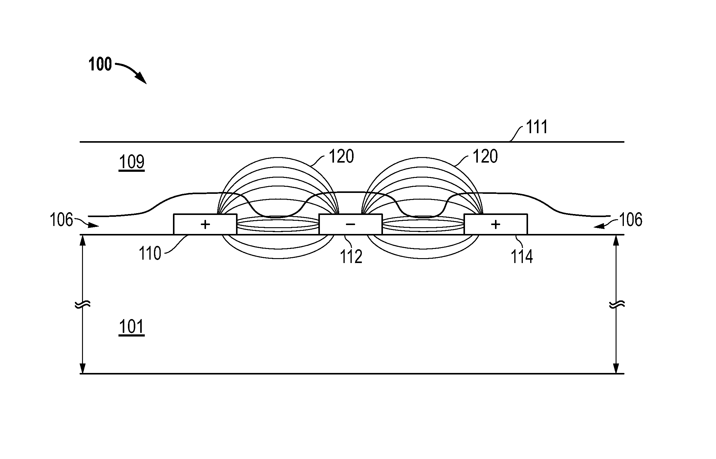
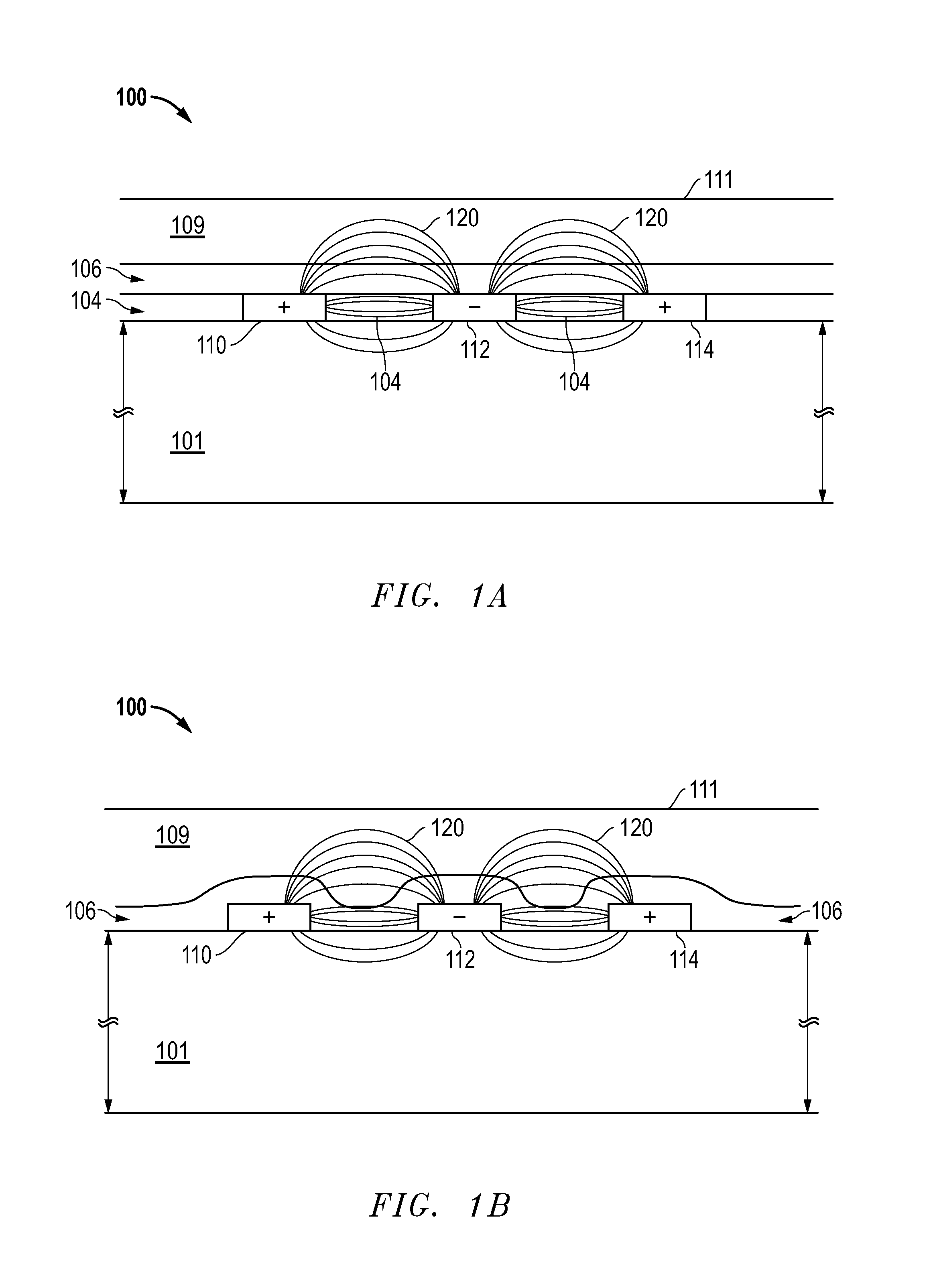
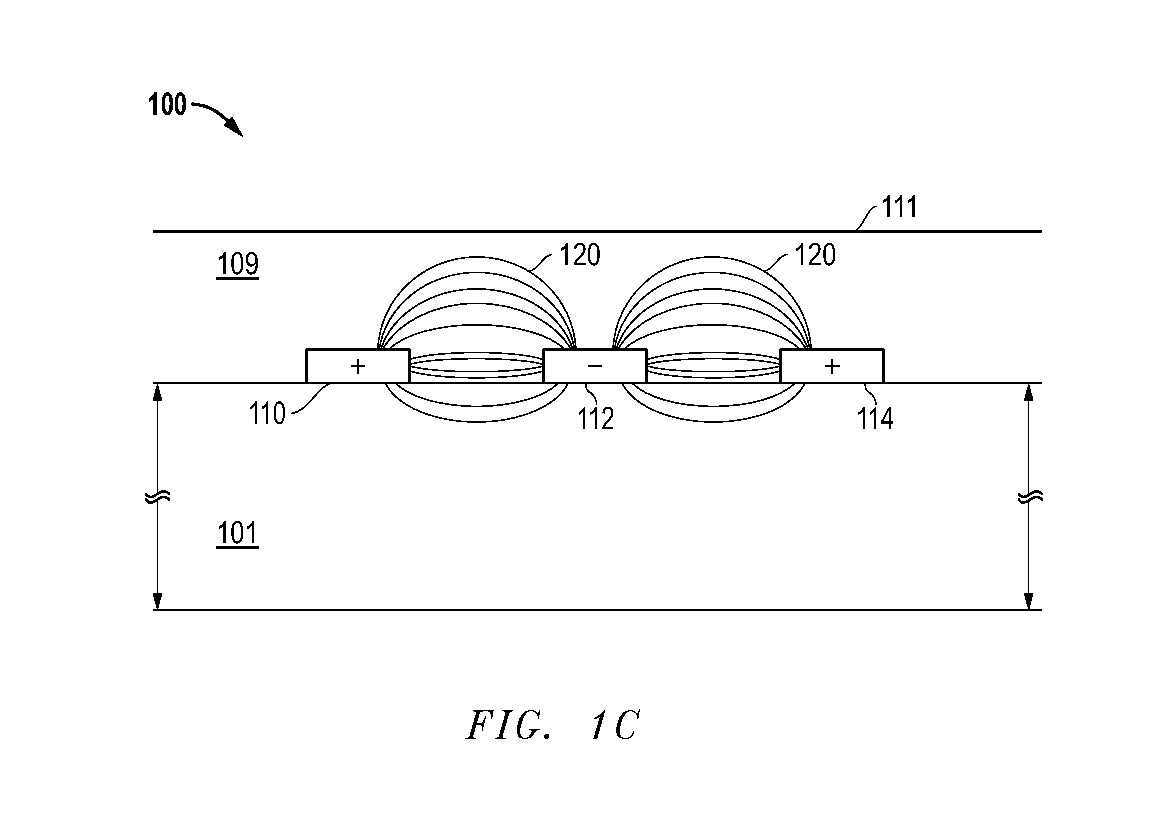
[0016]Rather than limiting use to lower RH ranges, the humidity and / or condensation sensor disclosed herein purposefully utilizes high RH condition measurements, even including condensation conditions. In one embodiment, the sensor may be a capacitive humidity sensor. FIGS. 1A-1C provide illustrative embodiments of a capacitive humidity sensor, though it will be recognized that many other capacitive humidity sensor structure arrangements may be utilized with the techniques disclosed herein. As shown in the FIG. 1A cross-section, sensor electrodes 110, 112 and 114 may be formed on a substrate 101 to form “fingers” of an interdigitated capacitive structure. It will be recognized that the capacitive structure may be formed by many electrodes arranged as shown in FIG. 1A. Capacitance measurements obtained between the electrodes may be utilized to determine humidity levels. Sensor electrodes may be any of a wide variety of conductive materials. Substrate 101 may be any of a wide variety ...


PUM


Abstract

A humidity sensor is provided having humidity levels approaching 100% relative humidity can be measured, as well as condensation measurements which appear as RH values “above 100%”. The humidity sensor is a capacitance based sensor. The capacitor(s) of the sensor is dimensioned so that substantial electric fields of the capacitor extend to the sensor/ambient air interface so that the conditions at the ambient side of the interface provide data for the sensor. In particular, the capacitance effects of moisture formation on the ambient side of the sensor/ambient air interface are utilized as part of the measurements so that relative humidity levels below and above 100% can be detected. The capacitor(s) of the sensor is dimensioned so that substantial electric fields of the capacitor extend to the air interface so that the conditions at ambient side of the interface provide data for the sensor.

Description

RELATED APPLICATIONS[0001]This application is related to the following application, concurrently filed on the same date as the present application, U.S. patent application Ser. No. ______, entitled “Capacitive Sensor Comprising Differing Unit Cell Structures”; the disclosures of which is expressly incorporated by reference herein in its entirety.TECHNICAL [0002]1. Field of the Invention[0003]The techniques disclosed herein relate to humidity sensors, and more particularly humidity sensors which may also be utilized for condensation measurements.[0004]2. Background[0005]A wide variety of types of sensors are utilized to measure gases and other ambient air conditions such as humidity. When relative humidity concentrations rise to high levels, moisture condensation on surfaces may occur. Condensation such as the formation of “fogging” or actual water droplets on a surface is a well-known problem. Condensation initially may result in fogging of windows and surfaces, causing visibility p...

Claims


Application Information

Patent Timeline
IPC IPC(8): G01N27/22
CPCG01N27/223
Inventor CUMMINS, TIMOTHYO'CONNELL, JOHN O.
Owner SILICON LAB INC
Why Eureka
Try Eureka