Microtome having an auto-rocking mode

Active Publication Date: 2014-01-30
LEICA BIOSYST NUSSLOCH
View PDF10 Cites 17 Cited by
  • Summary
  • Abstract
  • Description
  • Claims
  • Application Information

AI Technical Summary

Benefits of technology

[0008]It is an object of the present invention to provide a microtome

Problems solved by technology

Compared to a purely rotational movement in one direction of rotation, such rocking movements are unergonomic for the user and, therefore, become uncomfortable over time.
T

Method used


Image

  • Microtome having an auto-rocking mode
  • Microtome having an auto-rocking mode
  • Microtome having an auto-rocking mode

Examples


Embodiment Construction

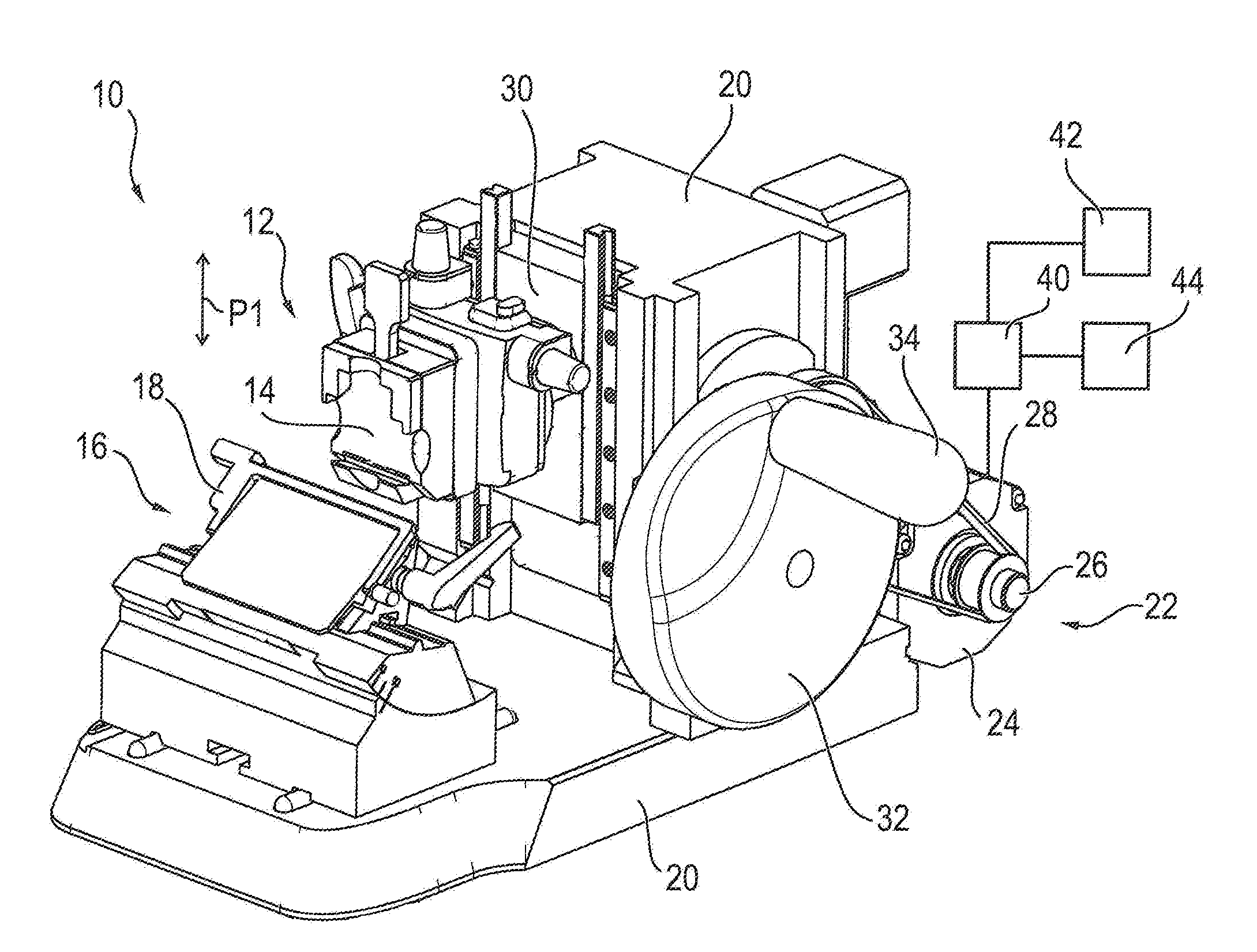
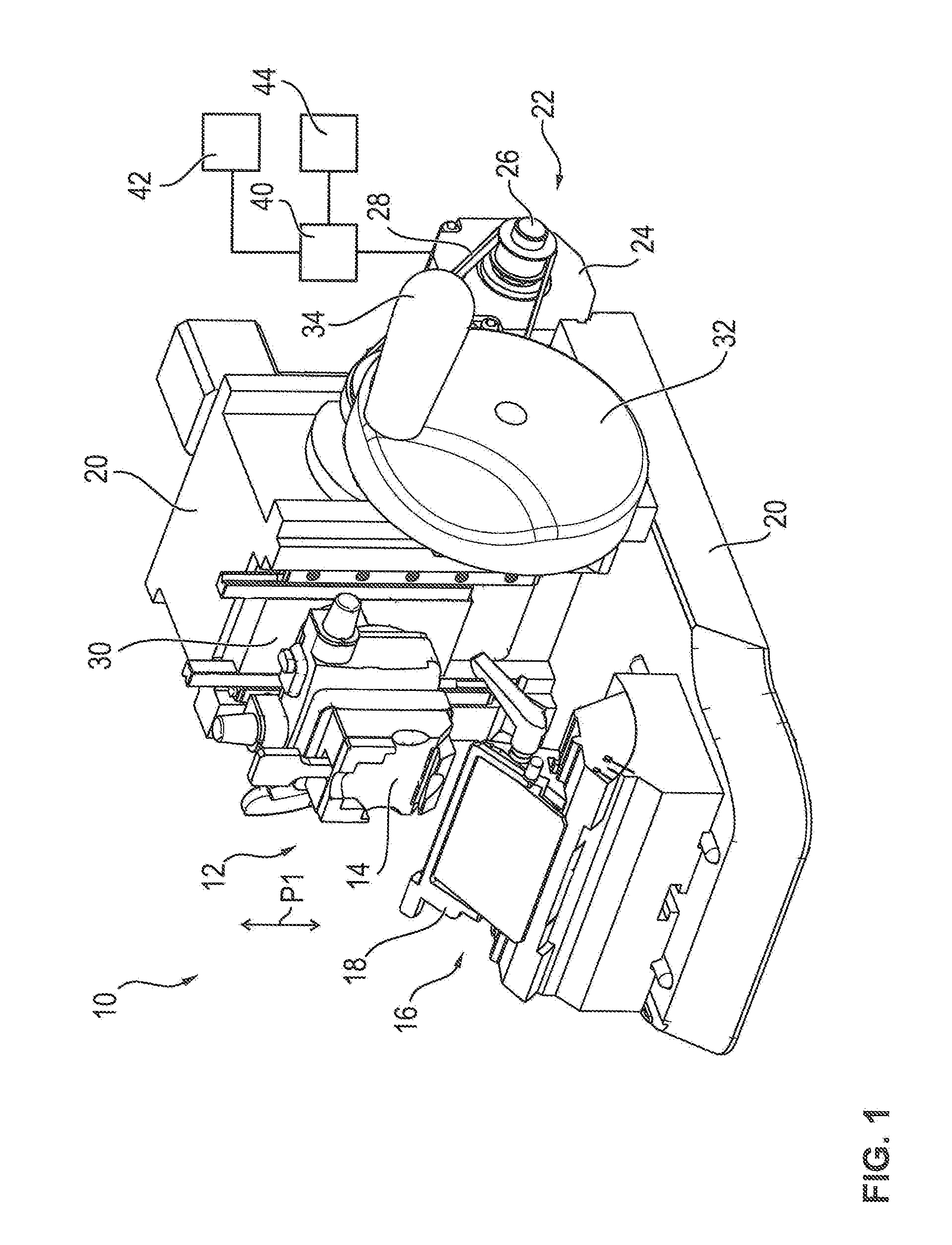
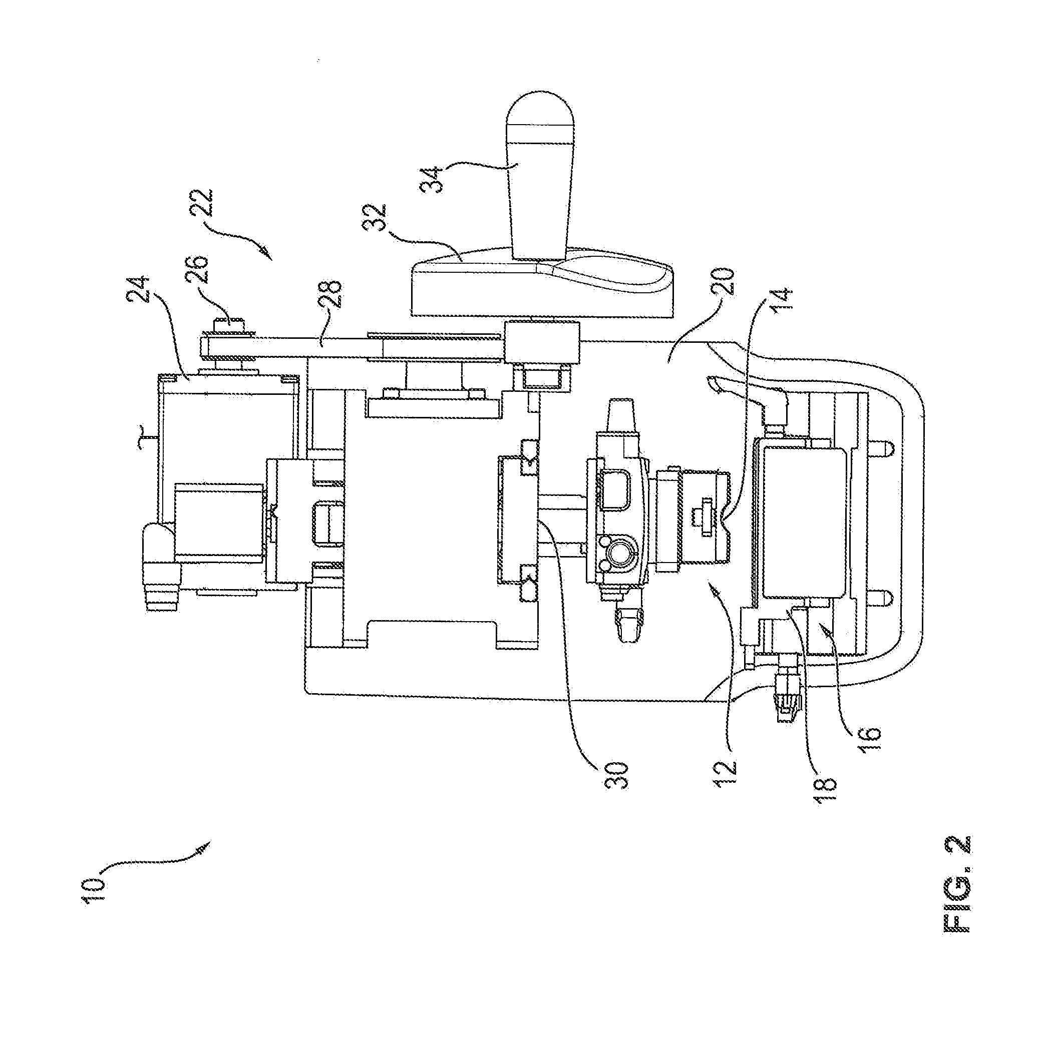
[0034]FIG. 1 shows a microtome 10 in schematic perspective view. The housing of microtome 10 has been omitted here to allow better viewing of the interior components. FIG. 2 shows a top view of the microtome of FIG. 1.

[0035]Microtome 10 includes a sample holder 12 in which the sample to be microtomed (e.g., a tissue sample) can be clamped by means of a chuck 14.

[0036]Microtome 10 further has a cutting unit 16 which, in the exemplary embodiment shown in FIG. 1, is in the form of a blade holder 18 capable of holding a blade or knife.

[0037]Cutting unit 16 is stationary relative to microtome frame 20, whereas sample holder 12 is movable relative to cutting unit 16 by a drive unit 22 in the direction of double-headed arrow P1 in a reciprocating manner, so that the sample received in sample holder 12 is cut by cutting unit 16 as a result of this reciprocating movement.

[0038]Drive unit 22 includes a motor 24 whose output shaft 26 is connected by a toothed belt 28 to a coupling mechanism 30...


PUM

PropertyMeasurementUnit
Angleaaaaaaaaaa
Lengthaaaaaaaaaa

Abstract

The present invention relates to a microtome (10) including a sample holder (12) a cutting unit (16), and a drive unit (22) capable of producing a relative movement between the sample holder (12) and the cutting unit (16) for cutting the sample. In addition, the microtome (10) has a handwheel (32) and an encoder (38). A control unit (40) controls the drive unit (22) as a function of the rotational movement of the handhweel (32) detected by the encoder (38) and in such a way that, in a first operating mode, the relative movement produced between the sample holder (12) and the cutting element (16) by the drive unit (22) when the handwheel (32) is rotated through a full revolution has a maximum first stroke length and that, in a second operating mode, the relative movement has a preset second stroke length shorter than the maximum first stroke length.

Description

CROSS REFERENCE TO RELATED APPLICATIONS[0001]This application claims priority of German patent application number 10 2012 106 845.3 filed Jul. 27, 2012, the entire disclosure of which is incorporated by reference herein.FIELD OF THE INVENTION[0002]The present invention relates to a microtome for cutting thin sections, including a sample holder for receiving a sample to be microtomed, a cutting unit for cutting the sample, and a drive unit for producing a relative movement between the sample holder and the cutting unit for cutting the sample. The microtome further has a manually operable handwheel and an encoder which detects rotational movement of the handwheel. A control unit controls the drive unit as a function of the rotational movement of the handwheel detected by the encoder.[0003]Microtomes are used to cut thin sections from samples. These sections are subsequently placed on a coverslip, suitably processed, and then examined under a microscope. The samples are, in particular,...

Claims


Application Information

Patent Timeline
IPC IPC(8): B26D5/00G01N1/06
CPCG01N1/06B26D5/00G01N2001/065Y10T83/4559Y10T83/87Y10T83/637B26D5/10
Inventor WALTER, ROLAND
Owner LEICA BIOSYST NUSSLOCH
Why Eureka
Try Eureka