
Eureka
For R&D, Eureka makes reading and utilizing patents & technical documents easy.
Eureka AIR
Designed for self-driven R&D workflows. Generate viable solutions, solve complex R&D challenges, empower your innovation with AI.

Eureka Materials
Designed for material experts only. Revolutionize your material R&D, from search, analyze, to developing new materials.

TechResearch
Generate reliable direction feasibility study reports for your R&D in just a few steps.

TechSeek
Discover and master advanced knowledge NOW. Basics, ideas, possibilities, all at once.

TechMind
As an expert in R&D Theories, TechMind can generates customized viable solutions instantly.

TechRisk
Analyze your overall solution with one click, know your potential R&D risks in advance.

TechMonitor
Get weekly tech updates, stay abreast of the latest tech innovations and key insights.
Hydraulic camshaft phaser
- Summary
- Abstract
- Description
- Claims
- Application Information
AI Technical Summary
Benefits of technology
Problems solved by technology
Method used
Image

Examples
Embodiment Construction
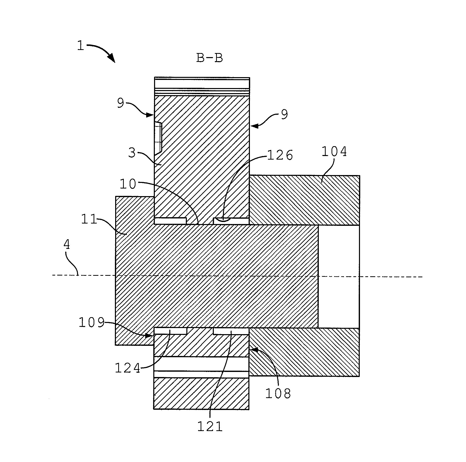
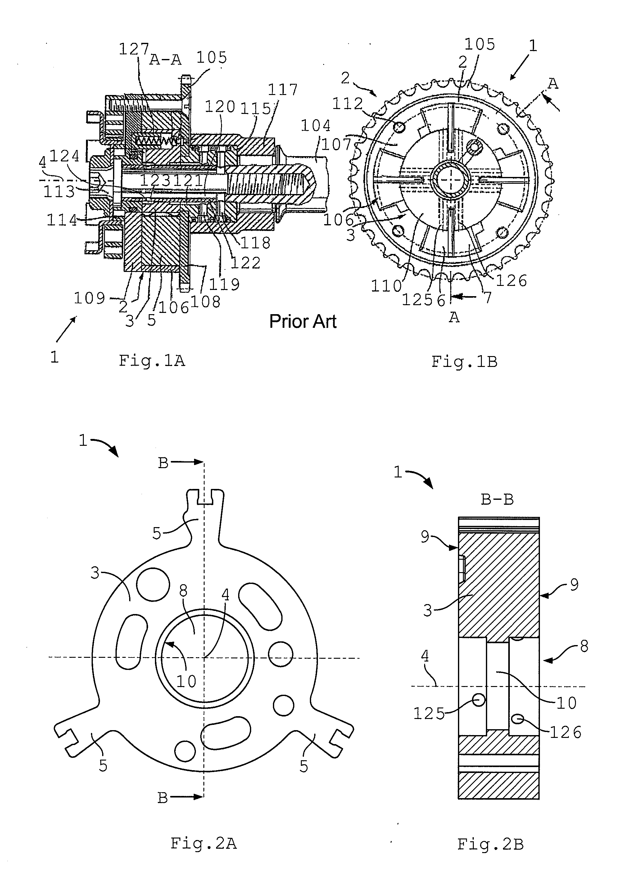
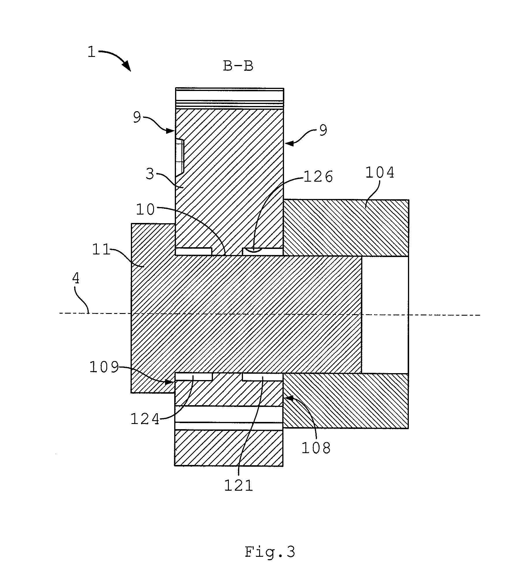
[0025]FIG. 1A shows an axial section along line A-A of a hydraulic camshaft phaser 1, which is shown in FIG. 1B in radial section. Accordingly, camshaft phaser 1 is attached to an end face of a camshaft 104 and includes an outer rotor 2 drivingly connected to a crankshaft and an inner rotor 3 non-rotatably connected to camshaft 104, the outer rotor and the inner rotor being rotationally adjustable relative to each other and arranged concentrically about a common axis of rotation 4. Outer rotor 2 is drivingly connected to the crankshaft via a drive sprocket 105 and has an outer ring 106, on whose inner circumference are arranged radial partition walls 107 which, together with first and second end plates 108, 109 and a rotor hub 110 of inner rotor 3, bound circumferentially distributed hydraulic chambers. The two end plates 108,109 and outer ring 106 are clamped together by axial screws 112. Rotor hub 110 of inner rotor 3, a bushing 114 and a rotary oil passage member 115 are jointly ...
PUM
 Abstract
Description
Claims
Application Information
 - R&D Engineer
- R&D Manager
- IP Professional
- Industry Leading Data Capabilities
- Powerful AI technology
- Patent DNA Extraction
Browse by: Latest US Patents, China's latest patents, Technical Efficacy Thesaurus, Application Domain, Technology Topic, Popular Technical Reports.
© 2024 PatSnap. All rights reserved.Legal|Privacy policy|Modern Slavery Act Transparency Statement|Sitemap|About US| Contact US: help@patsnap.com