Swing damper with disc brakes and its control mechanism

a technology of disc brakes and dampers, which is applied in the direction of vibration dampers, springs/dampers, load-engaging elements, etc., can solve the problems of increasing the size being unsuitable, loosening the ability of the swing damper to tension the disc brakes, and increasing the risk of braking the construction by means of outer action, etc., to achieve convenient use of tensioning and improve service time and reliability

Inactive Publication Date: 2014-01-30
BALTROTORS SIA
View PDF17 Cites 6 Cited by
  • Summary
  • Abstract
  • Description
  • Claims
  • Application Information

AI Technical Summary

Benefits of technology

[0004]Taking into account known construction of swing dampers and wishes of industry it can be concluded that there is a need for compact swing damper with ea...

Problems solved by technology

Such a construction increases a size of the swing damper and not suitable for compact size excavators, grabbers and grapplers, as well as increases a risk to brake said construction by means of outer action.
Disadvantage of the design is a use of the disc spring, which during longer service period looses its elasticity and therefore looses its ability to te...

Method used


Image

  • Swing damper with disc brakes and its control mechanism
  • Swing damper with disc brakes and its control mechanism
  • Swing damper with disc brakes and its control mechanism

Examples


Embodiment Construction

[0013]The invention is described by the following drawings:

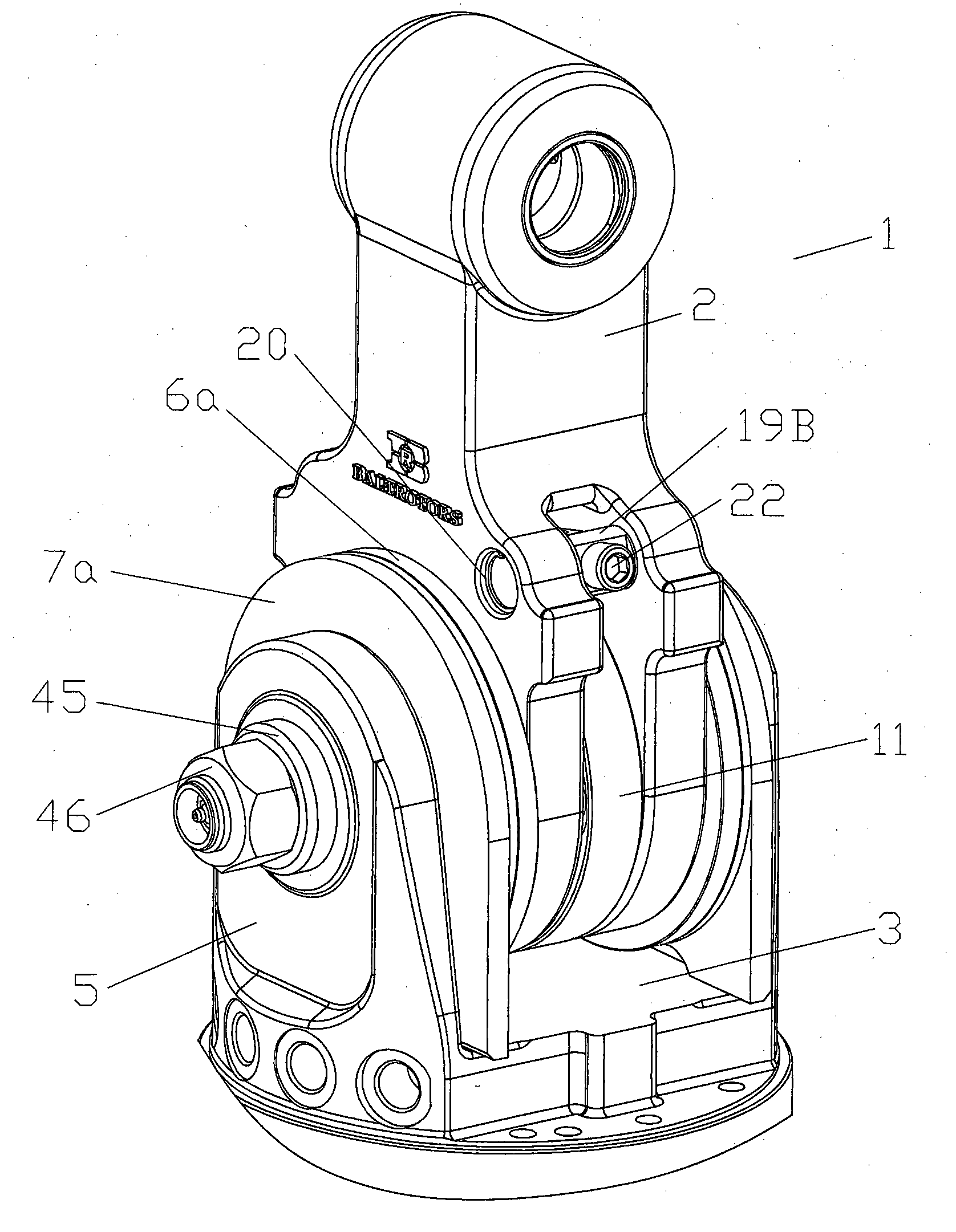
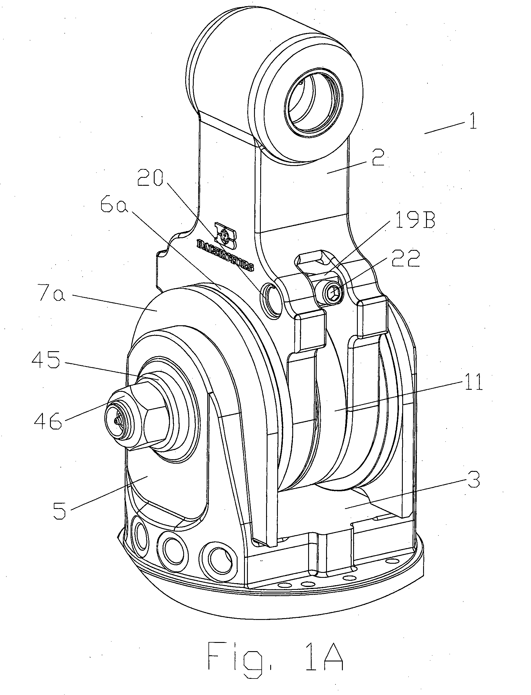
[0014]FIG. 1A—illustrates a swing damper 1 in assembled state;

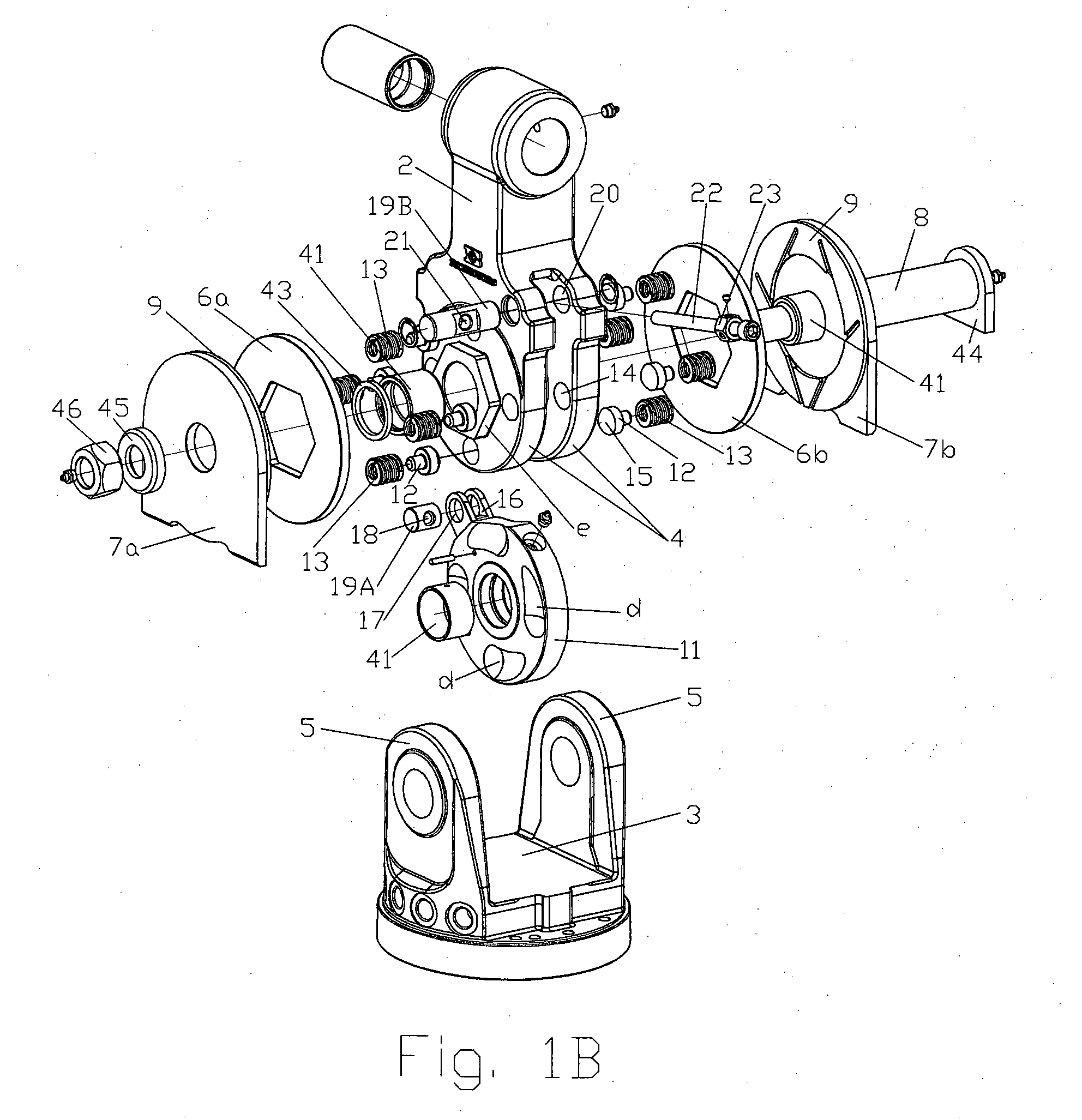
[0015]FIG. 1B—illustrates a swing damper 1 with braking discs 6a, 6b, 7a and 7b in disassembled state;

[0016]FIG. 2—illustrates a swing damper 1 in a cross section;

[0017]FIG. 3A—illustrates a position of a tensioning element 10 of braking disc 6a, 6b, 7a and 7b of a swing damper 1 and control means 30 at the beginning of service, when new braking discs 6a, 6b, 7a and 7b are installed;

[0018]FIG. 3B—illustrates a position of a tensioning element 10 of braking disc 6a, 6b, 7a and 7b of a swing damper 1 and control means 30 at the end of service, when braking discs 6a, 6b, 7a and 7b are wear out to such a state, that they have to be changed;

[0019]FIG. 4—illustrates a tensioning element 10 and a control means 30 in axonometric view;

[0020]FIG. 5A—illustrates an adjusting disc 11;

[0021]FIG. 5B—illustrates a cavity “d” of an adjusting disc 11 in a cross section E-E (see FI...


PUM


Abstract

The invention refers to swing dampers, in particular to the swing dampers having disc brakes. A Swing damper (1) for damping work elements, comprising an upper part (2) having at least two lugs (4) and a lower part (3) having at least two lugs (5), where brake discs (6a, 6b; 7a, 7b) are arranged between the lugs 4 of the upper part 2 and the lugs 5 of the lower part 3. The Swing damper (1) characterized in that a tensioning element (10) and associated control means (30) are provided in the cut-out “a” formed between the two lugs (4) of the upper part (2), providing a pressing of the brake discs (6a, 6b; 7a, 7b) and therefore damping a swing.

Description

FIELD OF THE INVENTION [0001]Invention refers to swing dampers, in particular to the swing dampers comprising disc brakes.[0002]Swing dampers usually are used in suspensions that connect a crane arm of a hydraulic crane to rotator, which drives crane's actuators: harvesters; grabs; grapples and the like hydraulic actuators. The swing damper dampens oscillations of the actuator during its operation.BACKGROUND OF THE INVENTION [0003]There is known U.S. Pat. No. 5,110,169 that describes swing damper comprising plurality of braking discs that tensioned by means of screw and disc spring. Assembly of disc brakes is disposed beyond and out of swinging connection. Such a construction increases a size of the swing damper and not suitable for compact size excavators, grabbers and grapplers, as well as increases a risk to brake said construction by means of outer action. Swing damper of similar construction is described in U.S. Pat. No. 4,335,914. There is known swing damper with disc construc...

Claims


Application Information

Patent Timeline
IPC IPC(8): F16F7/02
CPCF16F7/023B66C3/005
Inventor MARTINSONS, ANDRIS
Owner BALTROTORS SIA
Why Eureka
Try Eureka