
Winch brake

a technology of winch brake and brake lever, which is applied in the direction of coupling-brake combination, freewheel clutch, hoisting equipment, etc., can solve the problems of lowering security and insufficient brake force of this design of winch brake, and achieve the effect of convenient user operation and convenient operation

Inactive Publication Date: 2014-01-30
LIFE STYLE METAL CO LTD
View PDF6 Cites 14 Cited by
  • Summary
  • Abstract
  • Description
  • Claims
  • Application Information

AI Technical Summary

Benefits of technology

The present invention is a winch brake that provides reliable and durable performance. It uses both a brake spring and a one-way bearing to stop the winch drum when no power is supplied, ensuring real-time performance and increased reliability and durability. Additionally, the deceleration clutch mechanism is easy to operate, making it easy for users to engage or disengage the winch.

Problems solved by technology

However, the automatic braking function of the aforesaid winch brake simply relies upon contact and friction between the outer perimeter of the brake spring and the inner perimeter of the brake drum.
The brake force of this design of winch brake is insufficient.
After a long use, the brake spring will wear, lowering the security.

Method used


Image

  • Winch brake
  • Winch brake
  • Winch brake

Examples


Embodiment Construction

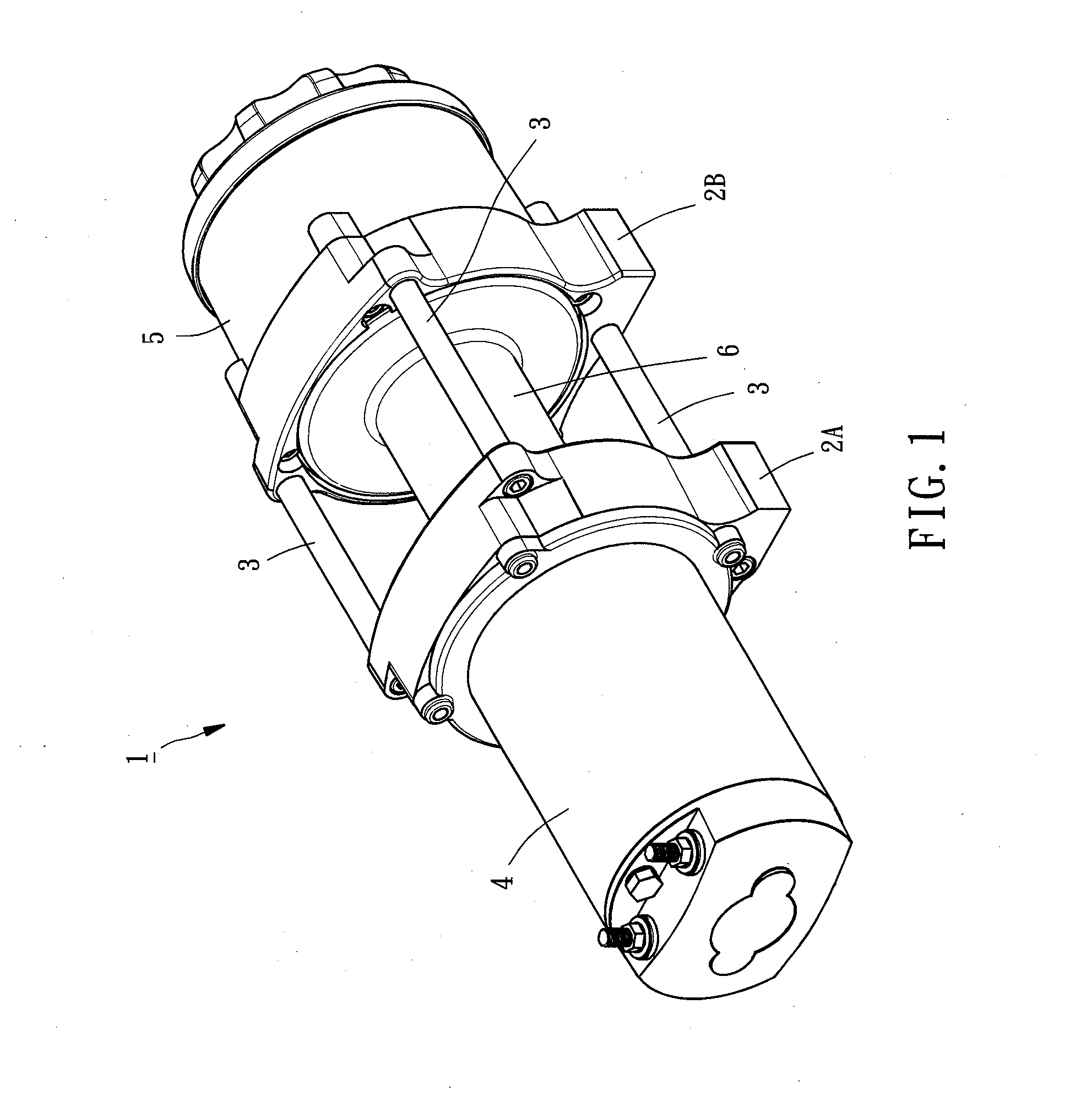
[0020]Referring to FIG. 1, a winch 1 is shown comprising two locating blocks 2A2B, two pairs of spacer rods 3 connected between the two locating blocks 2A2B to keep the two locating blocks 2A2B apart at a predetermined distance, a motor 4 mounted at an outer side of one locating block 2A opposite to the spacer rods 3, a deceleration clutch mechanism 5 mounted at an outer side of the other locating block 2B opposite to the spacer rods 3, and a winch drum 6 coupled between the two locating blocks 2A2B to wind up a cable (not shown). Thus, the winch 1 the motor 4 as the power source to provide a rotary driving force that is transferred through the deceleration clutch mechanism 5 to rotate winch drum 6, thereby pulling in or letting out the cable.

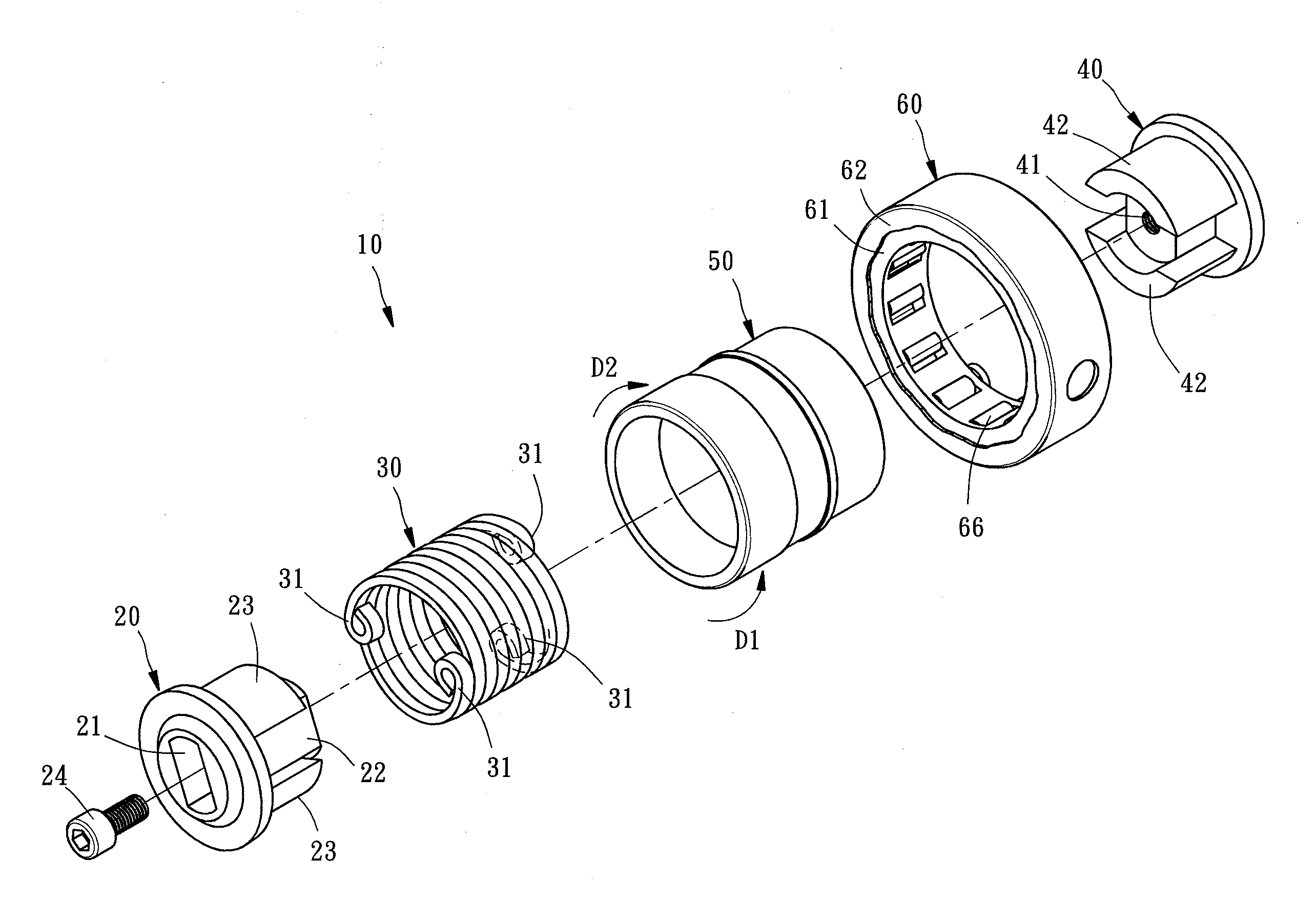
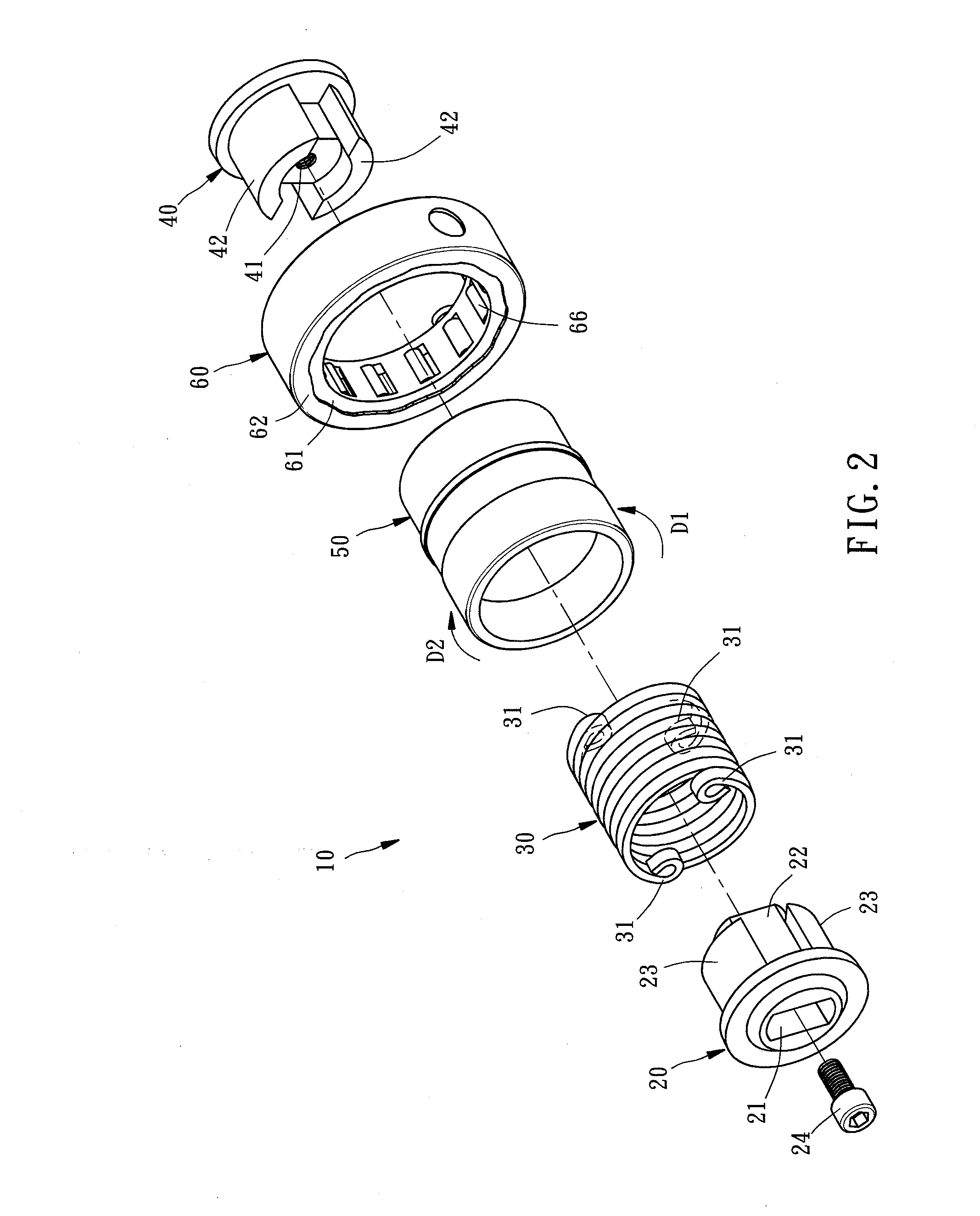
[0021]Referring to FIGS. 2-5 and FIG. 1 again, a winch brake 10 in accordance with the present invention is shown installed in the aforesaid winch 1. As illustrated, the winch brake 10 comprises a brake bush 50, a driving block 20, a brake spri...


PUM


Abstract

A winch clutch includes a driving block and a driven block respective connected to a motor and a transmission shaft of a deceleration clutch mechanism of a winch, the driving block and the driven block each having two spaced protruding flanges, a brake spring mounted between the driving block and the driven block and having retaining end portions disposed at two opposite ends thereof and respectively engaged into gaps between the protruding flanges of the driving block and gaps between the protruding flanges of the driven block, a brake bush accommodating the driving block, the driven block and the brake spring, and a one-way bearing fixedly mounted in the winch around the brake bush to limit rotation of the brake bush in a first direction. Thus, the winch brake has the characteristics of high reliability and high durability.

Description

BACKGROUND OF THE INVENTION[0001]1. Field of the Invention[0002]The present invention relates to winch devices of international patent classification B66D and more particularly, to a winch brake for power winch, which can effectively prevent accidents and enhance operational safety.[0003]2. Description of the Related Art[0004]A winch is a mechanical device that is used to pull in or let out a cable, thereby lifting or lowering a load. A winch is generally equipped with a brake that is provided between the motor and the speed reducing mechanism to prevent the drum from turning when power is off, ensuring the safety of the use of the winch.[0005]A winch brake is known comprising a driving block rotatable by a motor, a driven block connected to a transmission shaft of a deceleration clutch mechanism, a brake spring set between the driving block and the driven block for allowing contraction or expansion of the coil diameter thereof subject to rotation of the driving block, and a brake d...

Claims


Application Information

Patent Timeline
Patent Type & Authority Applications(United States)
IPC IPC(8): B66D5/00
CPCB66D5/00B66D1/14B66D5/06F16D41/067F16D41/064
Inventor LIN, TA-YU
Owner LIFE STYLE METAL CO LTD
Learn More