Ro system and method for disinfecting lines of the ro system

a technology of ro system and disinfection line, which is applied in the field of ro system, can solve problems such as harm to the health of patients, and achieve the effect of gentle decontamination

Active Publication Date: 2014-01-30
VIVONIC GMBH
View PDF3 Cites 12 Cited by
  • Summary
  • Abstract
  • Description
  • Claims
  • Application Information

AI Technical Summary

Benefits of technology

[0003]It is the object of the present invention to indicate an RO system of the kind in question that permits a gentle decontamination at least of the area of the permeate line, while ensuring at the same time that no pump gets damaged due to the cleaning operation.
[0007]Moreover, according to the invention a permeate return-line section which terminates in the permeate return line downstream of the valve arranged therein branches off from the permeate supply line upstream of the termination of the recirculation line into the permeate supply line, and a pressure holding valve is arranged in the permeate return-line section. This has the effect that the RO system can continue its operation also in the disinfection mode and uninterruptedly produces permeate that can flow off through the permeate return-line section into the supply tank of the RO system. When no additional permeate is needed in the recirculation circuit of the ozonized permeate, the whole amount of the fresh permeate produced during recirculation flows off through the pressure holding valve to the supply tank in that in the return line section before the valve such a pressure is built up that it exceeds the closing force of the valve. Instead of such a pressure holding valve, a valve may also be provided that is e.g. electrically controlled by a control device of the RO system.

Problems solved by technology

The line system of an RO system must be decontaminated from time to time because otherwise organic deposits may settle in the interior of the lines and associated functional units, such as valves, etc., and it may be infested by germs that might be harmful to the health of patients treated by means of the dialysis devices.

Method used


Image

  • Ro system and method for disinfecting lines of the ro system
  • Ro system and method for disinfecting lines of the ro system

Examples


Embodiment Construction

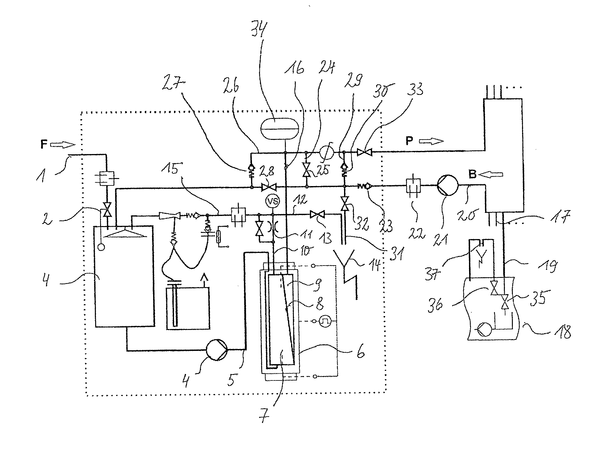
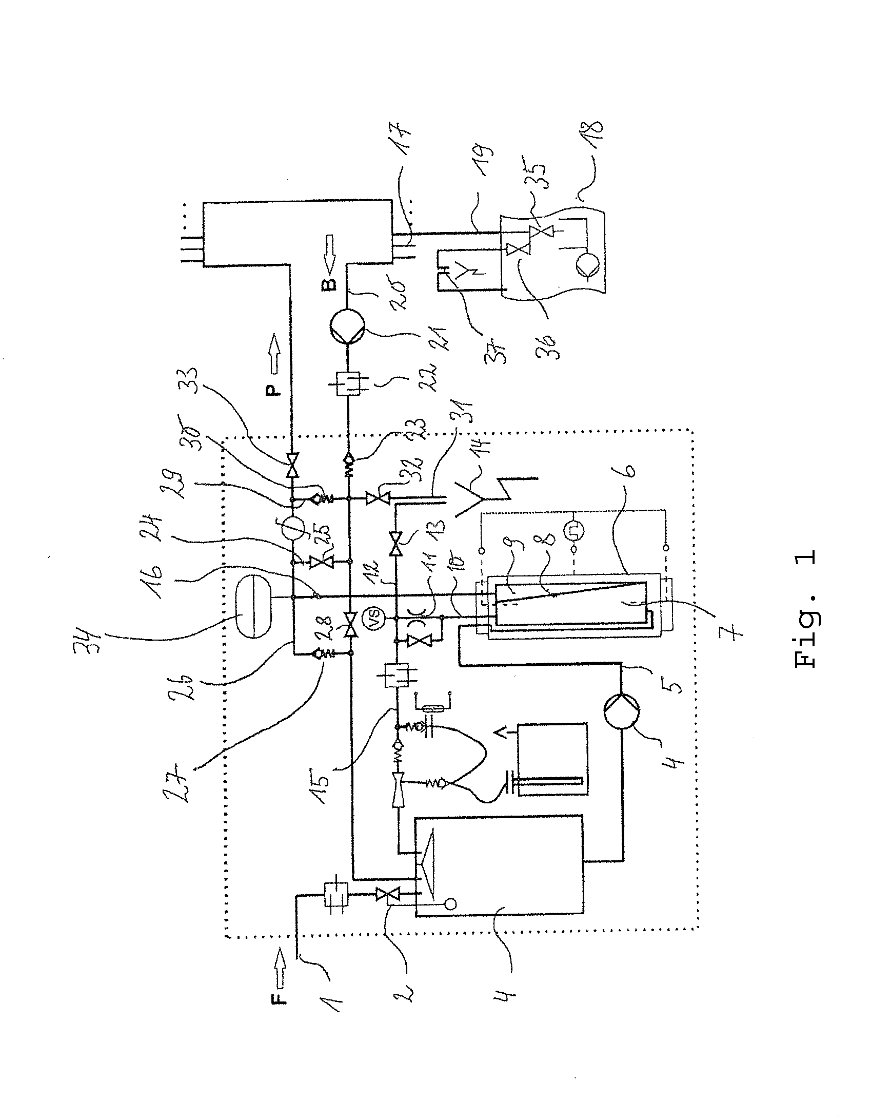
[0016]Described are only the components of the FIGURE that are of importance to the present invention.

[0017]Liquid is supplied through a line 1 to the RO system, the liquid passing via an inlet valve 2 into the supply tank 3. The liquid in the supply tank 3 is supplied by means of a pump 4 through a line 5 to an RO filter module 6, the primary chamber 7 of which is separated by a membrane 8 from the secondary chamber 9.

[0018]Concentrate is discharged from the primary chamber 7 through a line 10 in which a throttle 11 provides the pressure prevailing in the primary chamber 7. The concentrate can either be discharged through a line 12, into which a valve 13 is integrated, into an outlet 14 or can be returned through a concentrate return line 15 into the supply tank 3.

[0019]Permeate flows out of the secondary chamber 9 through a permeate supply line 16 to connections 17 of dialysis devices that in an illustrated example can be supplied with permeate through a respective branch line 19....


PUM

PropertyMeasurementUnit
voltageaaaaaaaaaa
currentaaaaaaaaaa
concentrationaaaaaaaaaa

Abstract

A circulation pump and an electrochemical ozone generator are integrated into the permeate return line of an RO system, and the permeate return line is connected in flow direction behind the circulation pump and the ozone generator by a recirculation line to the permeate supply line, which can form a closed circuit where the ozonized permeate circulates until all organic contaminants have been killed or decomposed by the ozone in that part of the line system. Valves are integrated, respectively, into the recirculation line and the permeate return line downstream of the branch of the recirculation line. During normal operation of the RO system, the recirculation line valve is connected for feeding connected dialysis devices while the permeate return line valve is open, so excessive permeate that was not taken by the dialysis devices can flow into the supply tank. Alternatively, the permeate can be discharged into an outlet.

Description

FIELD OF THE INVENTION[0001]The present invention refers to an RO system with which ultrapure water is preferably produced for the operation of dialysis devices. The RO system comprises an RO filter module which is subdivided by a membrane into a primary chamber and a secondary chamber, an atmospherically ventilated supply tank in which a raw-water supply line terminates, a line which leads from the lower end of the supply tank to the primary chamber and into which a pump is integrated, a concentrate line which leads away from the primary chamber and preferably leads back to the supply tank, and a permeate supply line which extends from the secondary chamber of the filter module and to which at least one dialysis device is connectable by means of a branch line or secondary ring line, wherein further, in flow direction behind the connection of the at least one dialysis device, an adjacent permeate return line leads back to the supply tank.BACKGROUND[0002]The line system of an RO syst...

Claims


Application Information

Patent Timeline
Patent Type & Authority Applications(United States)
IPC IPC(8): C02F1/44C02F1/78B01D65/02
CPCA61M1/1656A61M1/169C02F1/4672C02F2103/026C02F2307/14C02F1/441C02F2209/04C02F2209/23A61M1/1688B01D61/08B01D61/10B01D61/243B01D61/58B01D65/022B01D2311/06B01D2311/25A61M1/1672A61M1/168A61M1/16
Inventor VOLKER, MANFRED
Owner VIVONIC GMBH
Why Eureka
Try Eureka