Discharge cell for ozone generator

a technology of ozone generator and discharge cell, which is applied in the direction of discharge tube main electrode, oxygen/ozone/oxide/hydroxide, non-electron-emitting electrode materials, etc., can solve the problems of affecting the production of semiconductors, critical problems, and reducing the concentration of ozone in the generated ozone gas

Inactive Publication Date: 2000-04-04
SUMITOMO PRECISION PROD CO LTD
View PDF2 Cites 41 Cited by
  • Summary
  • Abstract
  • Description
  • Claims
  • Application Information

AI Technical Summary

Problems solved by technology

Where high purity oxygen gas is used as the raw material gas, however, the concentration of ozone in the generated ozone gas tends to be reduced with time.
This is a critical problem.
However, it has recently been found that, where nitrogen gas is used in combination with oxygen gas, ozone gas to be supplied contains metal impurities, which adversely influence the semiconductor production.
This is because, where nitrogen gas is added to high purity oxygen gas for the generation of ozone gas, the generated ozone gas contains nitrogen oxides as side products, which may deteriorate or corrode the interior surface of the stainless steel pipe.
The use of a catalytic gas other than nitrogen gas reduces the production of the metal impurities in the site supplied with ozone gas.
However, this approach requires an additional pipeline for supplying the catalytic gas to the oxygen gas pipeline, thereby complicating the system.
Therefore, this approach is still unsatisfactory.
Therefore, where the dielectric layer contains titanium dioxide in an amount great enough to suppress the reduction in the ozone concentration, the dielectric layer may flake off or crack due to a difference in the thermal expansibility between the dielectric layer and the electrode during the use of the discharge cell.

Method used


Image

  • Discharge cell for ozone generator
  • Discharge cell for ozone generator
  • Discharge cell for ozone generator

Examples


first embodiment

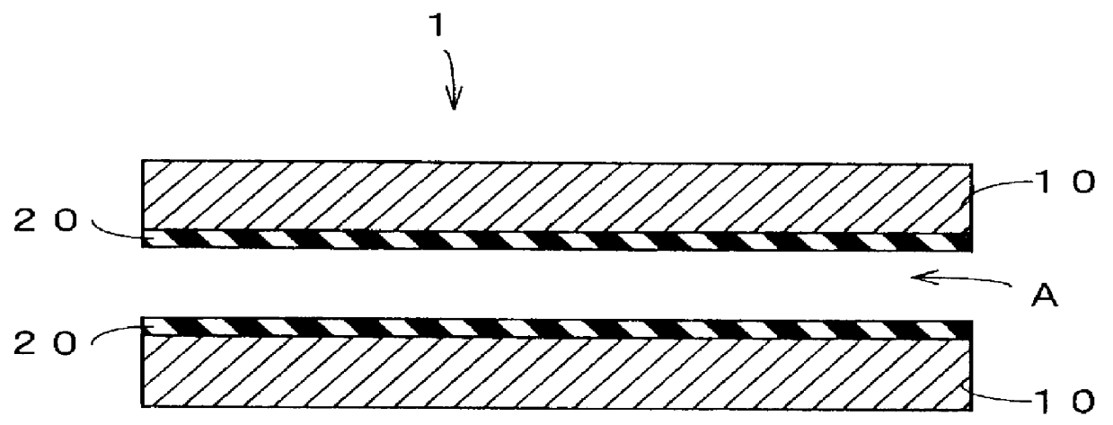
As shown in FIG. 1, a discharge cell 1 of plate type for an ozone generator has a pair of 1.0-mm thick iron electrodes 10, 10 disposed in an opposed spaced relation with a discharge space A therebetween and dielectric coating layers 20, 20 respectively formed on opposed electrode surfaces of the electrodes 10, 10. The discharge cell 1 is adapted to generate ozone gas by supplying thereto high purity oxygen gas as a raw material gas while causing non-arc discharge in the discharge space A defined between the electrodes 10, 10.

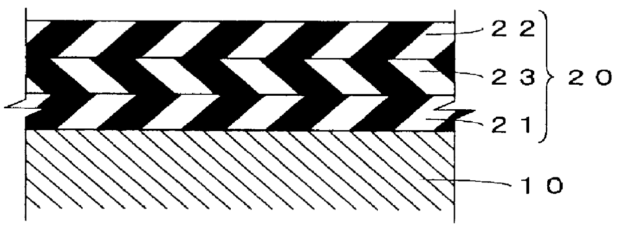
The dielectric layers 20, 20 are respectively formed on the electrodes 10, 10 by sintering a ceramic material on the electrodes 10, 10. As shown in FIG. 2, the dielectric layers 20, 20 each include a first dielectric layer 21 contacting the electrode 10, a second dielectric layer 22 exposed to the discharge space A and a third dielectric layer 23 interposed between the first dielectric layer 21 and the second dielectric layer 22. The sintering for the formation ...

second embodiment

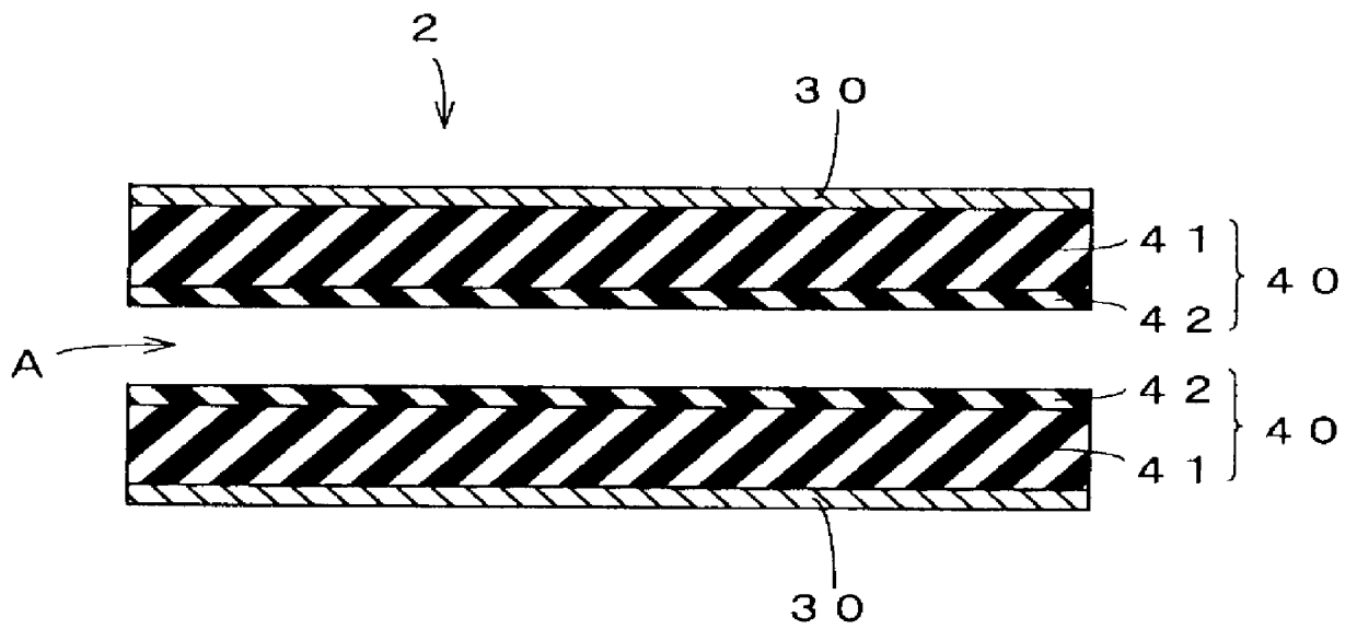
FIG. 3 shows a second embodiment of the present invention. A discharge cell 2 for an ozone generator according to this embodiment has substantially the same construction as the ozone generator discharge cell 1 described above in that dielectric layers 40, 40 are respectively provided on opposed electrode surfaces of a pair of electrodes 30, 30, but is different from the ozone generator discharge cell 1 in that the dielectric layers 40, 40 are each comprised of a preformed plate and the electrodes 30, 30 each comprised of a thin silver film having a thickness of 5 to 20 .mu.m are respectively bonded to the back sides of the dielectric plate layers 40, 40.

The dielectric layers 40, 40 each include a first dielectric layer 41 of an Al.sub.2 O.sub.3 plate or the like, and a second dielectric layer 42 formed on a surface of the first dielectric layer 41 and containing titanium dioxide in a metal element ratio of not lower than 10 wt %. The formation of the second dielectric layer 42 is ac...

experiment 1

Discharge cells (Samples 1 to 3) each including dielectric coating layers 20 as shown in FIG. 1 in accordance with the present invention were fabricated by employing dielectric layers (ceramic layers) respectively having different compositions as shown in Tables 2 to 4. Comparative discharge cells (Samples 4 to 6) as shown in FIG. 1 were fabricated by employing dielectric layers (ceramic layers) respectively having different compositions as shown in Tables 5 to 7. Ozone generators were fabricated in conformity with specifications as shown in Table 1 by employing these discharge cells. With the use of each of the ozone generators thus fabricated, ozone gas was generated by supplying high purity (99.995% pure) oxygen gas as a raw material gas to the ozone generator. A change in the ozone concentration in the generated ozone gas with time was observed. The results are shown in FIG. 4.

The dielectric layers each had a thickness of 0.1 mm. The contents of ceramic materials in the dielectr...


PUM

PropertyMeasurementUnit
thicknessaaaaaaaaaa
thicknessaaaaaaaaaa
thicknessaaaaaaaaaa

Abstract

A discharge cell for use in an ozone generator is provided which can suppress a time-related reduction in ozone concentration without adding a catalytic gas such as nitrogen gas to oxygen gas as a raw material gas. The discharge cell includes a pair of electrodes disposed in an opposed spaced relation with a discharge space therebetween, and a dielectric layer of a three-layer structure consisting of three ceramic dielectric layers successively stacked on at least one of the electrodes, wherein a first dielectric layer of the dielectric layer contacting the one electrode contains no titanium dioxide, wherein a second dielectric layer of the dielectric layer exposed to the discharge space contains titanium dioxide in a metal element ratio of not lower than 10 wt %.

Description

1. Field of the InventionThe present invention relates to a discharge cell for use in an ozone generator and, more particularly, to a discharge cell which is suitable for an ozone generator for semiconductor production.2. Description of the Background ArtDischarge cells for use in ozone generators are generally classified into a plate type and a tube type. Such a discharge cell, whichever type it falls in, has a pair of electrodes spaced with a discharge space therebetween, and a dielectric layer provided on a surface of at least one of the electrodes. Generation of ozone gas is achieved by passing a raw material gas such as oxygen gas through the discharge space.It is a conventional practice to employ a glass plate as the dielectric layer for the discharge cell. However, the glass plate dielectric layer generally has a great thickness because glass has a small dielectric constant. For this reason, ceramics which have greater dielectric constants than glass are often used for the di...

Claims


Application Information

Patent Timeline
Patent Type & Authority Patents(United States)
IPC IPC(8): C01B13/11H05H1/24
CPCC01B13/11H05H1/24C01B2201/34H05H1/2406
Inventor NAKATSUKA, SUGURU
Owner SUMITOMO PRECISION PROD CO LTD
Why Eureka
Try Eureka