Outer rotor type motor

a rotor type, motor technology, applied in the direction of windings, magnetic circuit rotating parts, magnetic circuit shapes/forms/construction, etc., can solve the problems of complicated lead wire handling and inability to simplify the handling of lead wires to draw the winding coils to the outside, etc., to achieve the effect of increasing the maximum number of rotations, simplifying the handling of lead wires, and large outpu

Inactive Publication Date: 2014-01-30
NAMIKI PRECISION JEWEL CO LTD
View PDF4 Cites 10 Cited by
  • Summary
  • Abstract
  • Description
  • Claims
  • Application Information

AI Technical Summary

Benefits of technology

[0019]The present invention is made as described above and therefore provides an advantageous effect described as follows. By inserting a plurality of lead wires installed in association with a plurality of stators to penetration portions of the stators, it is possible to lead them to only one side of the axial direction and draw them to the outside.
[0020]Therefore, it is possible to simplify the handling of lead wires of wiring coils in a plurality of stators without impairing various advantages of an outer rotor type motor that a large output can be obtained even in the case of a relatively small diameter size, a wiring coil can be thinned and shortened, the maximum number of rotations can be increased by reduction of the diameter size, and the reliability can be improved.

Problems solved by technology

However, since there are provided a plurality of stators and a plurality of winding coils corresponding to the stators respectively, there is a problem that it is not possible to simplify the handling of lead wires to draw the winding coils to the outside.
Thus, in the related art, handling of the lead wires is complicated.

Method used


Image

  • Outer rotor type motor
  • Outer rotor type motor
  • Outer rotor type motor

Examples


Embodiment Construction

[0027]An embodiment of the present invention is described based on the drawings. Also, in the following explanation, the “axial direction” means the direction of the center axis of a stator, rotor or drive shaft. Moreover, the “radial direction” means the direction orthogonal to the above-mentioned axial direction.

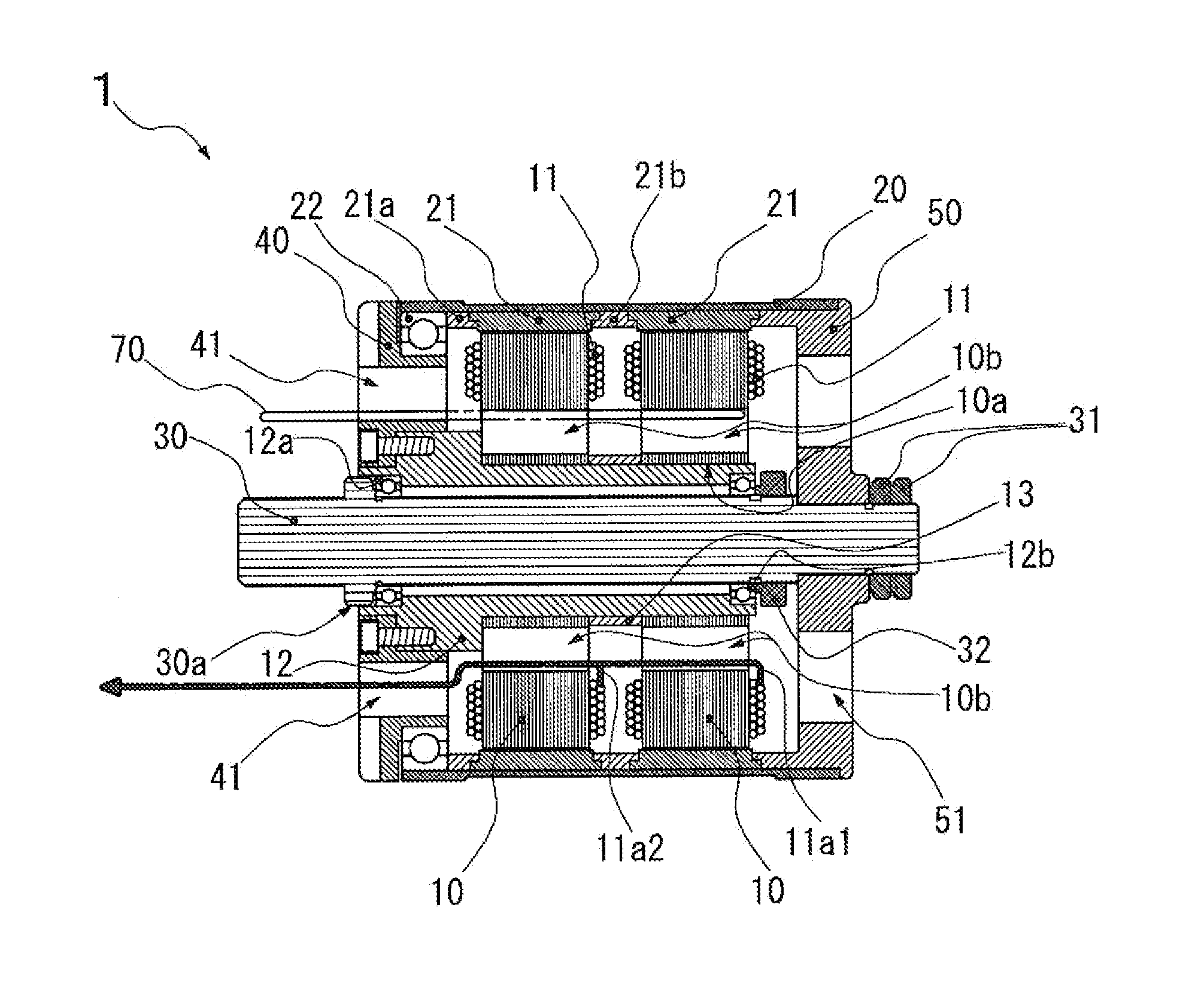
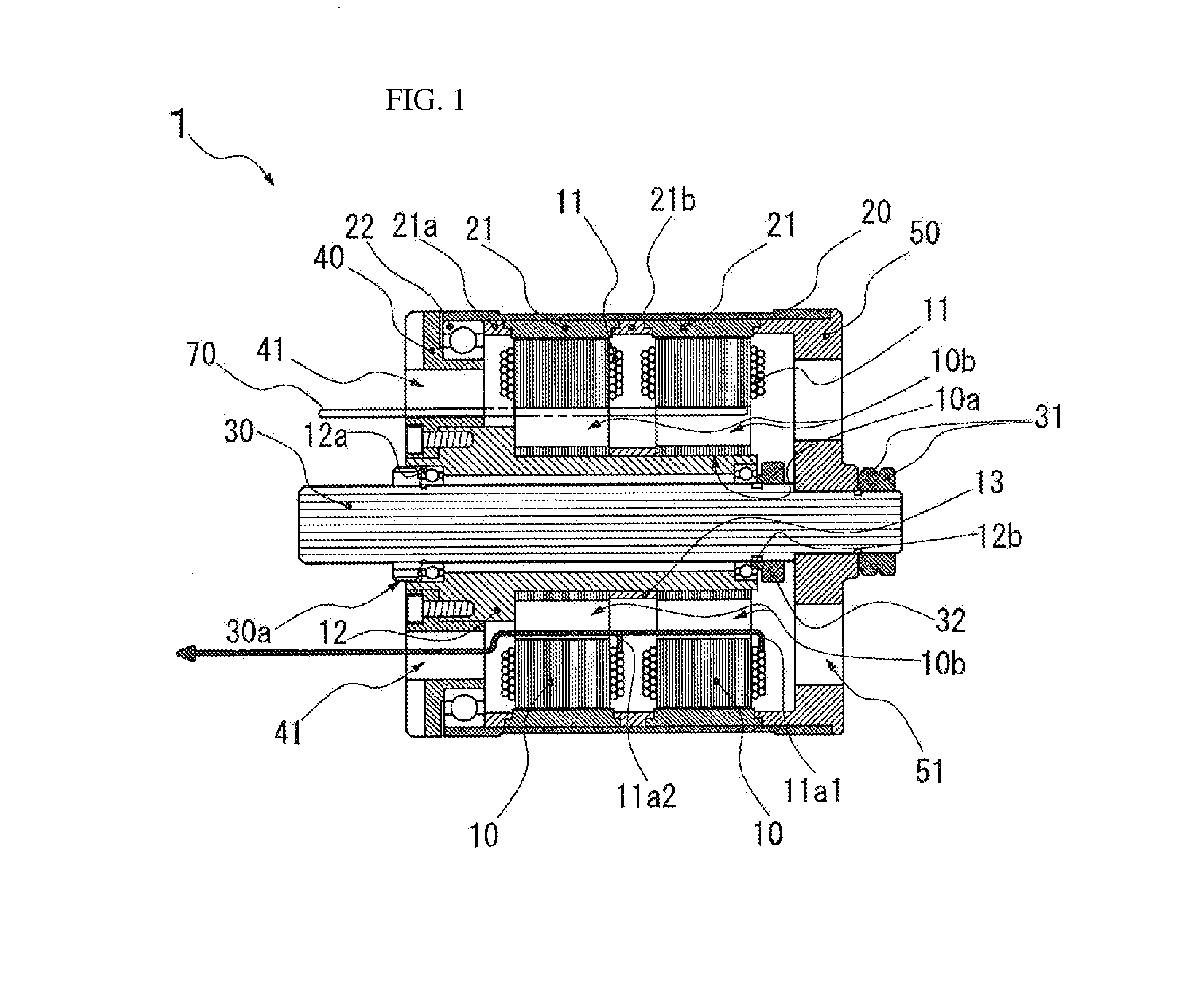
[0028]FIG. 1 illustrates one example of an outer rotor type motor according to the present invention. This outer rotor type motor 1 includes a plurality of stators 10 arranged in the axial direction, a rotor 20 that is supported so as to rotate around the plurality of stators 10, a drive shaft 30 that is integrally installed with the rotor 20, a winding coil 11 wound for each of the stators 10, a magnet 21 fixed to the rotor 20 in association with each of the stators 10, a rigid support member 40 that fixedly supports the plurality of stators in an unrotatable manner from one end side of the axial direction, and a rotation support member 50 that rotates with respect to the...


PUM


Abstract

To provide an outer rotor type motor configured so that the lead wires of the winding coils for the stators are routed simply. An outer rotor type motor is provided with stators arranged in the axial direction, a rotor supported so as to rotate around the stators, a drive shaft provided integrally with the rotor, winding coils respectively wound on the stators, and magnets affixed to the rotor so as to respectively correspond to the stators. The outer rotor type motor is configured so that the rotor and the drive shaft are rotated by the magnetic action between the winding coils and the magnets. A penetration portion extending in the axial direction is provided in at least one of the stators, and the lead wires of the winding coils are inserted through the penetration portion and led to the outside.

Description

TECHNICAL FIELD [0001]The present invention relates to an outer rotor type motor in which a rotor rotates around the outer periphery of a stator. Specifically, the present invention relates to an outer rotor type motor preferably used as a motor of a small electric aircraft and the like.BACKGROUND ART [0002]In the related art, for example, as described in Patent Document 1, this kind of invention includes a brushless motor having: a drive shaft (2); a plurality of stators (15, 16) arranged in the outer periphery of the drive shaft; a drive wheel (21) in which the central part is fixed to the outer periphery of the drive shaft and which extends in the diameter direction of the drive shaft; a plurality of cylindrical rotors (26, 27) which is fixed to the outer periphery of the drive wheel, extends in the same concentric shape as the drive shaft from the drive wheel to both sides of the drive shaft direction, and is arranged in the outer peripheries of the stators; and a plurality of b...

Claims


Application Information

Patent Timeline
Patent Type & Authority Applications(United States)
IPC IPC(8): H02K1/27H02K9/06H02K9/22H02K5/22
CPCH02K1/2786H02K9/22H02K9/06H02K5/22H02K1/20H02K3/50H02K16/00H02K21/22H02K5/225H02K9/223H02K1/2791
Inventor ARAI, KAZUO
Owner NAMIKI PRECISION JEWEL CO LTD
Why Eureka
Try Eureka