3D Polarized Eyewear

a polarized eyewear and stereoscopic technology, applied in the field of stereoscopic display apparatus and methods, can solve the problems of not being well suited to use in 3d imaging glasses, complicating the manufacture of 3d polarization glasses, and general use of linear polarized light, so as to improve the differentiation of left- and right-eye imaging, reduce cross-talk, and increase the amount of light

Inactive Publication Date: 2014-01-30
SOL GRID
View PDF4 Cites 48 Cited by
  • Summary
  • Abstract
  • Description
  • Claims
  • Application Information

AI Technical Summary

Benefits of technology

[0016]It is a feature of the present invention that it uses a linear polarizer with added spatial polarization azimuth control to provide viewing glasses that allow improved differentiation of left- and right-eye imaging for stereoscopic viewing. Advantageously, embodiments of the present invention improve existing fabrication processes and provide viewing glasses that allow increased amounts of light and reduced cross-talk over existing solutions.

Problems solved by technology

However, the use of linearly polarized light is generally disadvantageous for this purpose, since the viewer's head must remain at the same angle to avoid cross-talk, a condition in which some portion of light intended for the left-eye image goes to the right eye and light intended for the right-eye image goes to the left eye.
Due to their inherent tint, imperfections in fabrication, and other factors, polarizers of this type, although they may serve well in sunglasses and other optical devices, are generally not well suited for use in 3D imaging glasses.
One problem in fabrication of this type of polarizer is in controlling the orientation of the polarization axis, when the polarized material is curved to form eyeglasses.
These fabrication restrictions for polarization axes and conventional practices for QWP axis alignment complicate the manufacture of 3D polarization glasses and drive up the cost.
Given the inherent difficulties and added steps that would be required for determining the polarization axis of the stretched materials that are conventionally used and changing axes appropriately for each pair of viewing glasses, there may be few options for mass-produced 3D viewing eyewear using conventional fabrication methods.

Method used


Image

  • 3D Polarized Eyewear
  • 3D Polarized Eyewear
  • 3D Polarized Eyewear

Examples


Embodiment Construction

[0037]Elements not specifically shown or described may take various forms well known to those skilled in the art. Figures shown and described herein are provided in order to illustrate key principles of operation and component relationships along their respective optical paths or fabrication techniques according to the present invention and are not drawn with intent to show actual size or scale. Some exaggeration may be necessary in order to emphasize basic structural relationships or principles of operation.

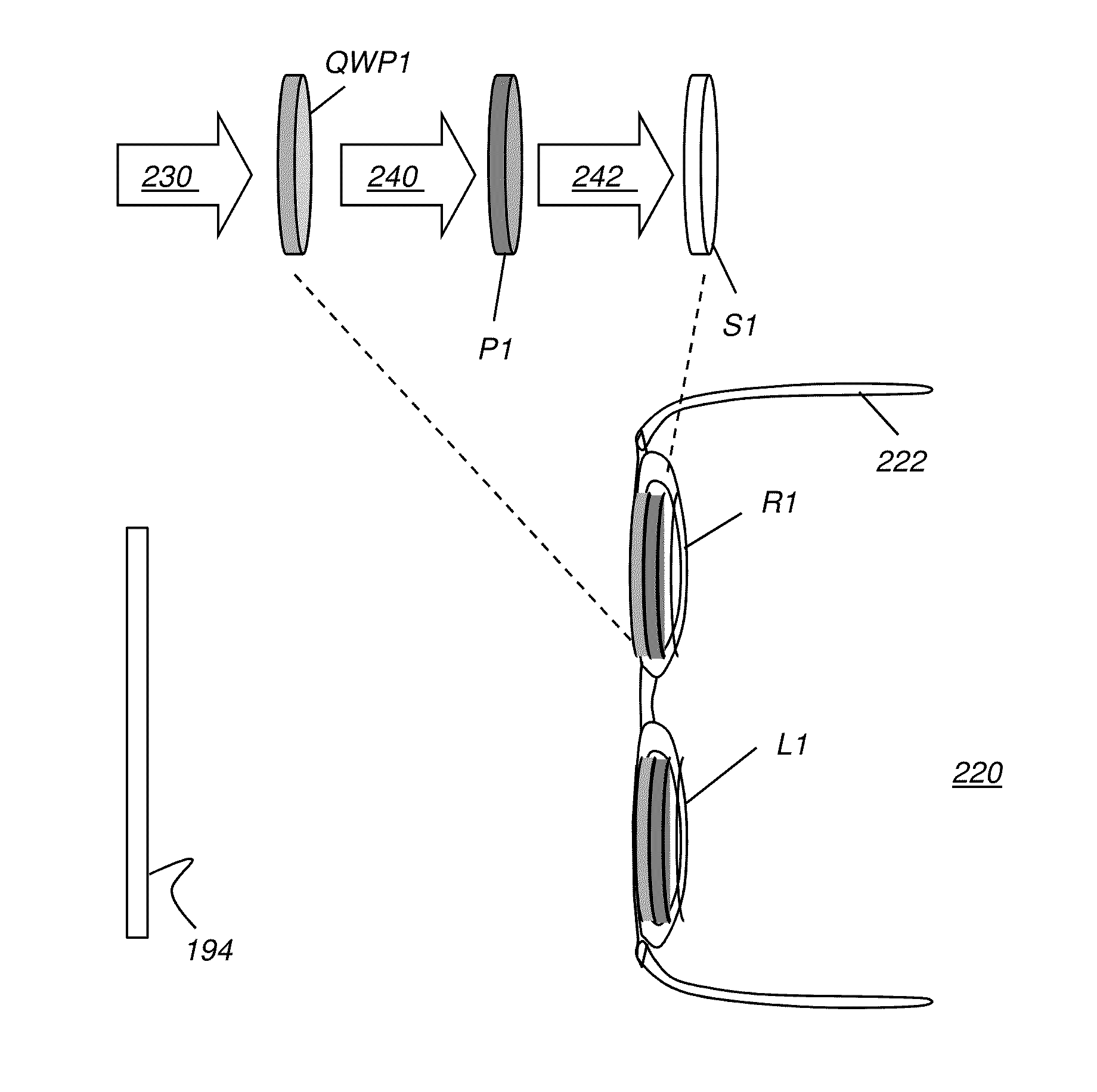
[0038]In the context of the present disclosure, the term “display surface” relates to any type of display surface or device that provides stereoscopic or 3D image content in which light for each of the left-eye and right-eye image content is provided having circular polarization. The respective image content for each eye is of opposite circular polarization. Thus, for example, where right circular polarization is used for the right-eye image, left circular polarization is used f...


PUM


Abstract

An article of eyewear for viewing a 3D display has at least one lens, wherein the at least one lens has a substrate lens material that is transparent to visible light and has a curved surface. A circular polarizer is formed on the substrate lens material and has a linear polarizer with a polarization axis and a quarter wave plate with a retardation axis that is inclined at substantially 45 degrees from the polarization axis along the curved surface. Either or both of the linear polarizer and the quarter wave plate are formed as sub-wavelength elongated structure devices.

Description

FIELD OF THE INVENTION[0001]This invention generally relates to apparatus and methods for viewing stereoscopic images and more particularly to eyewear for viewing stereoscopic displays that separate left-eye from right-eye images using polarization.BACKGROUND OF THE INVENTION[0002]Stereoscopic projection is a growing area of particular interest for the entertainment industry. Presentation of three-dimensional (3D) images or perceived stereoscopic content affords the viewer an enhanced visual experience, in the home theater setting or in larger venues such as movie theaters. Stereoscopic systems have been implemented using film, in which two sets of films and projectors simultaneously project orthogonal polarizations, one for each eye, termed a “left-eye image” and a “right-eye image” in the present disclosure. With digital projection and display, more options for image presentation are available, so that even a single projector or display device can be used to provide separate left-...

Claims


Application Information

Patent Timeline
Patent Type & Authority Applications(United States)
IPC IPC(8): G02B27/26G02B30/25
CPCG02B5/3058G02B30/25
Inventor KESSLER, DAVIDMATERA, PASQUALE
Owner SOL GRID
Why Eureka
Try Eureka