Systems and methods for current control of power conversion systems

a power conversion system and current control technology, applied in the field of integrated circuits, can solve the problems of low measurement accuracy of conventional current control schemes, and achieve the effects of reducing sampling errors, reducing sampling errors, and reducing measurement errors

Active Publication Date: 2014-01-30
ON BRIGHT ELECTRONICS SHANGHAI
View PDF7 Cites 135 Cited by
  • Summary
  • Abstract
  • Description
  • Claims
  • Application Information

AI Technical Summary

Benefits of technology

[0025]Many benefits are achieved by way of the present invention over conventional techniques. For example, some embodiments of the present invention sample a current sensing signal at a middle point of an on-time period to reduce the sampling errors associated with sampling twice the current sensing signal during the on-time period. In another example, certain embodiments of the present invention sample the current sensing signal at the middle point of an on-time period to reduce the sampling errors associated with sampling the current sensing signal shortly after the beginning of the on-time period. In yet another example, some embodiments of the present invention accurately detect the end of a demagnetization process without including a time period related to resonance into the demagnetization period to reduce measurement errors thereof.

Problems solved by technology

However, the conventional current control schemes often suffer from low measurement accuracy.

Method used


Image

  • Systems and methods for current control of power conversion systems
  • Systems and methods for current control of power conversion systems
  • Systems and methods for current control of power conversion systems

Examples


Embodiment Construction

[0041]The present invention is directed to integrated circuits. More particularly, the invention provides systems and methods for current control. Merely by way of example, the invention has been applied to constant current control of power conversion systems. But it would be recognized that the invention has a much broader range of applicability.

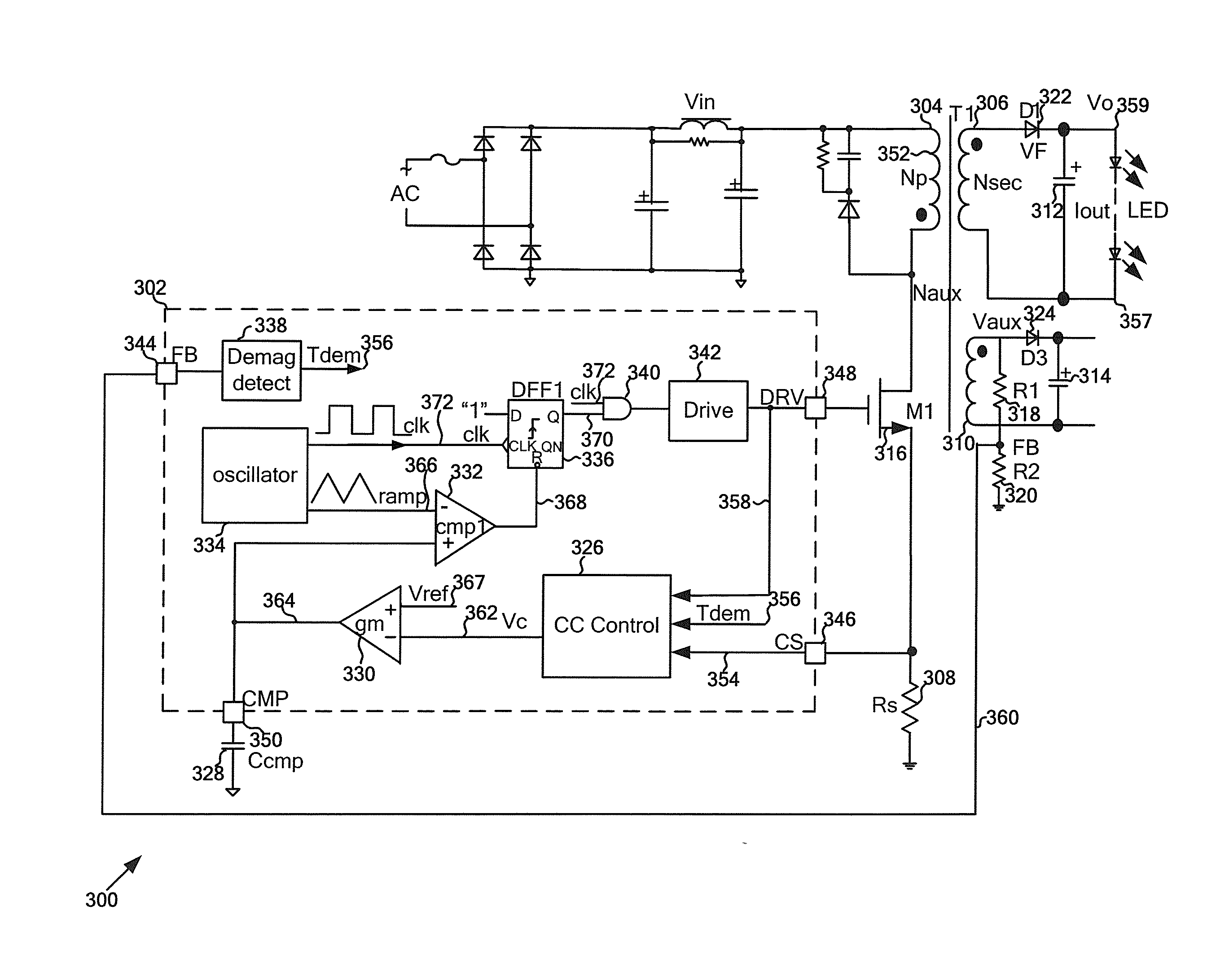
[0042]FIG. 3(A) is a simplified diagram showing a power conversion system configured to operate in the continuous conduction mode (CCM) and / or in the discontinuous conduction mode (DCM) according to an embodiment of the present invention. This diagram is merely an example, which should not unduly limit the scope of the claims. One of ordinary skill in the art would recognize many variations, alternatives, and modifications. The power conversion system 300 includes a controller 302, a primary winding 304, a secondary winding 306, a current sensing resistor 308, an auxiliary winding 310, three capacitors 312, 314 and 328, two resistors 318 an...


PUM


Abstract

System and method for regulating an output current of a power conversion system. An example system controller for regulating an output current of a power conversion system includes a driving component, a demagnetization detector, a current-regulation component, and a signal processing component. The driving component is configured to output a drive signal to a switch in order to affect a primary current flowing through a primary winding of the power conversion system. The demagnetization detector is configured to receive a feedback signal associated with an output voltage of the power conversion system and generate a detection signal based on at least information associated with the feedback signal. The current-regulation component is configured to receive the drive signal, the detection signal and a current-sensing signal and output a current-regulation signal based on at least information associated with the drive signal, the detection signal, and the current sensing signal.

Description

1. CROSS-REFERENCES TO RELATED APPLICATIONS[0001]This application claims priority to Chinese Patent Application No. 201210258359.X, filed Jul. 24, 2012, commonly assigned, incorporated by reference herein for all purposes.2. BACKGROUND OF THE INVENTION[0002]The present invention is directed to integrated circuits. More particularly, the invention provides systems and methods for current control. Merely by way of example, the invention has been applied to constant current control of power conversion systems. But it would be recognized that the invention has a much broader range of applicability.[0003]FIG. 1 is a simplified diagram showing a conventional flyback power conversion system. The power conversion system 100 includes a primary winding 110, a secondary winding 112, an auxiliary winding 114, a power switch 120, a current sensing resistor 130, two rectifying diodes 160 and 168, two capacitors 162 and 170, and two resistors 164 and 166. For example, the power switch 120 is a bip...

Claims


Application Information

Patent Timeline
Patent Type & Authority Applications(United States)
IPC IPC(8): H02M3/335H05B44/00
CPCH02M3/33507H05B45/382Y02B20/30H02M1/0009H02M3/156H02M1/08H02M3/33515
Inventor ZHANG, YUNCHAOFANG, LIEYI
Owner ON BRIGHT ELECTRONICS SHANGHAI
Why Eureka
Try Eureka