

Method for Allocating Multi-UEs' Sounding Reference Signal (SRS) Uplink Resources and eNB
- Summary
- Abstract
- Description
- Claims
- Application Information
AI Technical Summary
Benefits of technology
Problems solved by technology
Method used
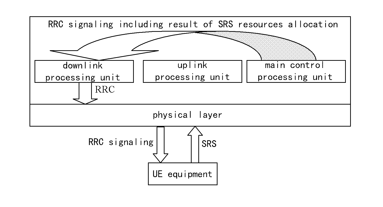
Image

Examples
embodiment 1
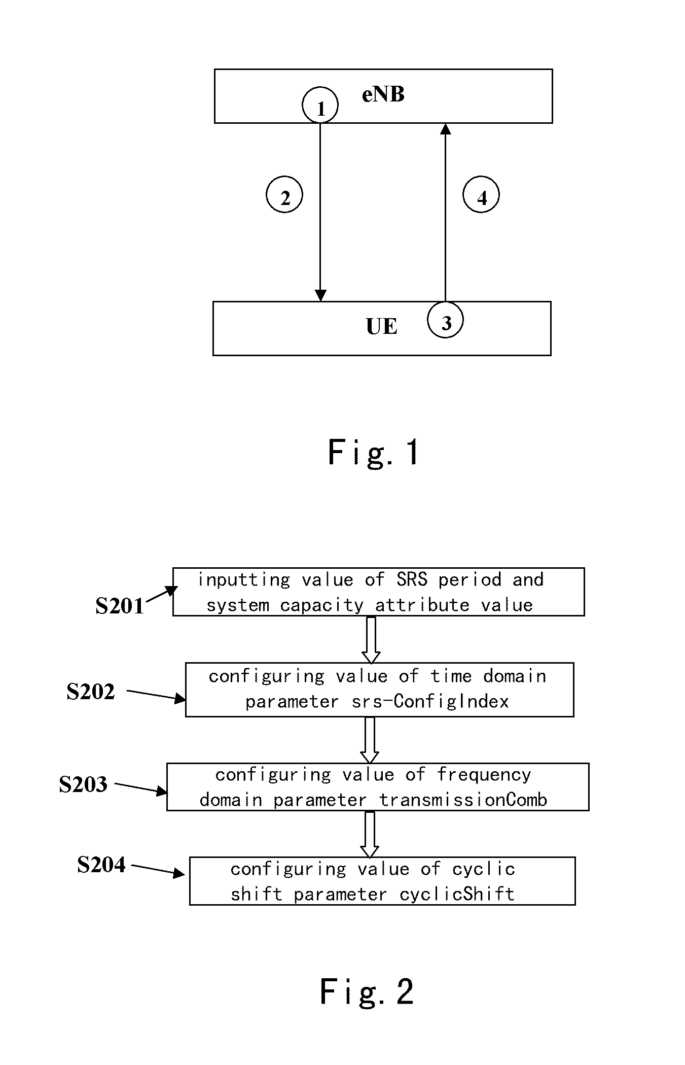
[0105]The detailed procedure of configuring value of parameters srs-ConfigIndex, transmissionComb, cyclicShift on the eNB side has be depicted as mentioned above. Hereinafter, an exemplary embodiment is represented for describing the method of configuring each of the aforementioned parameters in detail.
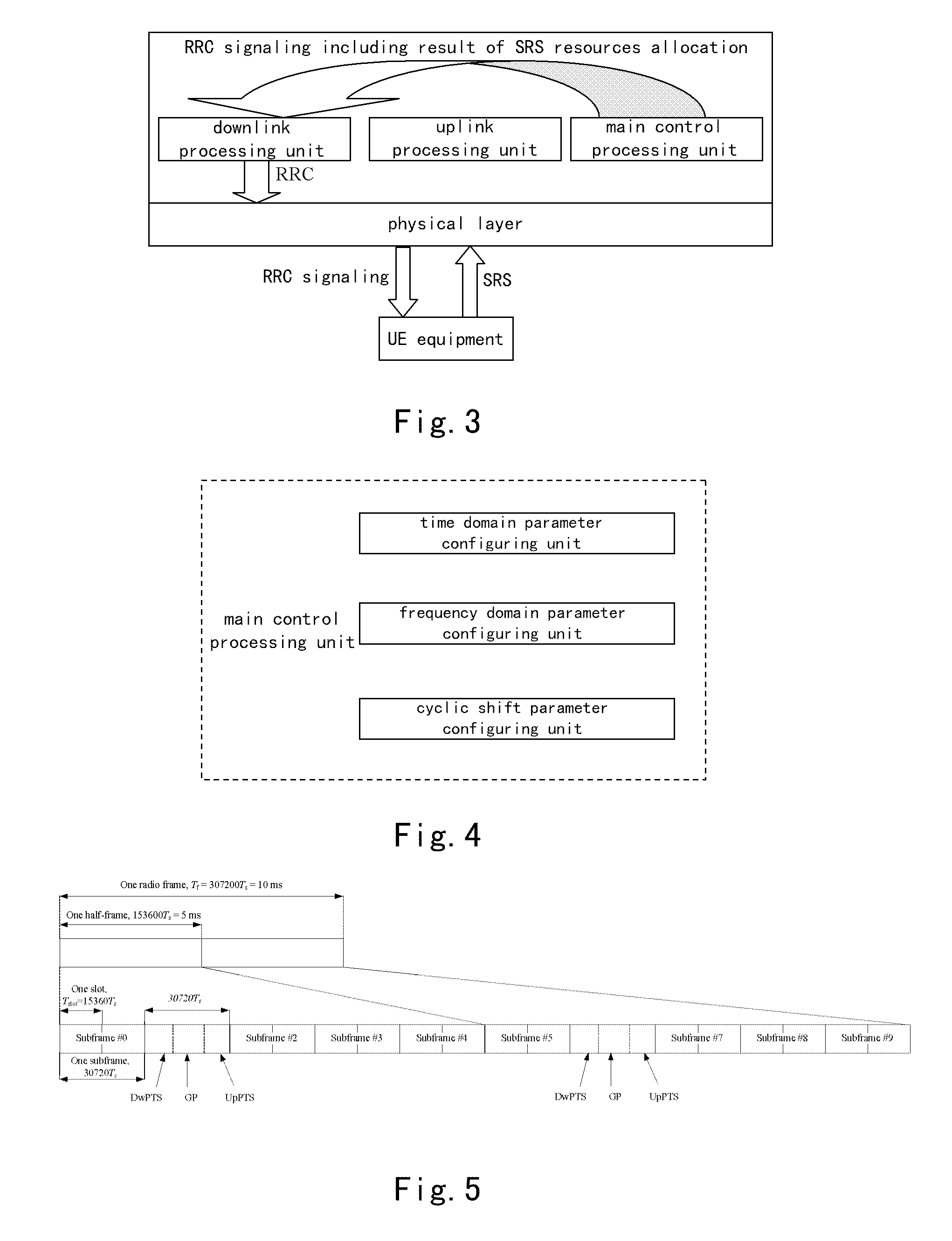
[0106]FIG. 5 shows the frame structure of TDD LTE according to the first embodiment.
[0107]In general, LTE comprises two types of frame structure, wherein the type 1 of frame structure is used for FDD LTE, and the type of frame structure is used for TDD LTE. The SRS resources allocation in the present embodiment is preferably adaptive for type 2 of frame structure of TDD LTE.
[0108]As shown in FIG. 5, in the present embodiment, the frame structure is type 2, and the time span of the system frame is 10 ms. Because the method configures all of UEs' uplink SRS transmission with identical period (TSRS), and there is only one time domain resource available for allocating SRS transmission in ...
embodiment 2
[0155]FIG. 12 shows the result of SRS resource allocation according to embodiment 2 of the present invention.
[0156]The embodiment shown in FIG. 12 describes the situation of SRS resources allocation based on different values of cyclic shift parameter cyclicShift.
[0157]In FIG. 12, the SRS minimum period supported by the system is 10 ms, and only the UpPTS resource of the sixth subframe can be used for SRS transmission allocation in each of the minimum periods. The SRS period (TSRS) is configured as 10 ms, and the maximum number of UE's SRS bearable on each UpPTS is 8 in the configured minimum period. The UE's SRS resource allocation is performed in the UpPTS of the sixth subframe of each system frame in the period, thus there are eight UEs needed to allocate uplink resources.
[0158]As shown in FIG. 12, because the maximum number of UE's SRS bearable on each UpPTS is 8 in the configured minimum period, the eight UEs' SRS are allocated into same UpPTS (ConfigIndex(Isrs)=21).
[0159]Then, ...
embodiment 3
[0160]FIG. 13 shows the result of SRS resource allocation according to embodiment 3 of the present invention.
[0161]The embodiment shown in FIG. 13 describes the situation of SRS resources allocation based on different values of frequency domain parameter transmissionComb.
[0162]In FIG. 13, the SRS minimum period supported by the system is 10 ms, and only the UpPTS resource of the sixth subframe can be used for SRS transmission allocation in each of the minimum periods. The SRS period (TSRS) is configured as 40 ms and the maximum number of UE's SRS bearable on each UpPTS is 2 in the configured minimum period. The UE's SRS resource allocation is performed in the UpPTS of the sixth subframe of each system frame in the period, thus there are eight UEs needed to allocate uplink resources.
[0163]As shown in FIG. 13, because the maximum number of UE's SRS bearable on each UpPTS is 2 in the configured minimum period, the eight UEs' SRS are allocated into four UpPTS (ConfigIndex(Isrs)=51, 61, ...
PUM
 Abstract
Description
Claims
Application Information