Spherical Sound Source for Acoustic Measurements

a sound source and acoustic measurement technology, applied in the direction of transducer casings/cabinets/supports, electrical transducers, frequency/directions obtaining arrangements, etc., can solve the problem of not being able to intuitively find and not being able to achieve the maximum spl deviation

Inactive Publication Date: 2014-01-30
VALTCHEV PLAMEN IVANOV +1
View PDF0 Cites 10 Cited by
  • Summary
  • Abstract
  • Description
  • Claims
  • Application Information

AI Technical Summary

Benefits of technology

[0019]Both high frequency compression drivers 12 of the coaxial loudspeakers 10 radiate in substantially conical space of about 90 degrees opening angle, defined by membrane cones 11, which is equivalent to about π / 2 solid angle spherical radiation.

Problems solved by technology

Even though this presumption might be true in the above mentioned case, in reality it is neither feasible nor practical.
Furthermore, every individual loudspeaker membrane does not radiate spherically, as its axial directivity index increases with frequency, thus further worsening the overall sound source directivity performance.
Dodecahedron sound source, unluckily, is characterized by its unsymmetrical mid-high frequency directivity pattern in whatsoever plane of measurement, and planes of maximum SPL deviation could not be intuitively found.
For precision acoustic measurement, however, concealing the actual sound source directivity performance couldn't help much.
The results of measurements might turn to be misleading anyway.
This cannot be achieved under conditions of interference, as the case is when multihedron loudspeaker arrangement is used, because just these interferences raise the directivity index value.

Method used


Image

  • Spherical Sound Source for Acoustic Measurements
  • Spherical Sound Source for Acoustic Measurements
  • Spherical Sound Source for Acoustic Measurements

Examples


first embodiment

DESCRIPTION OF THE FIRST EMBODIMENT

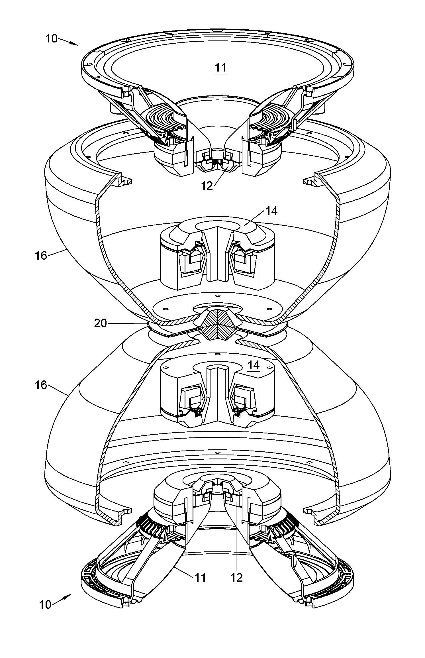
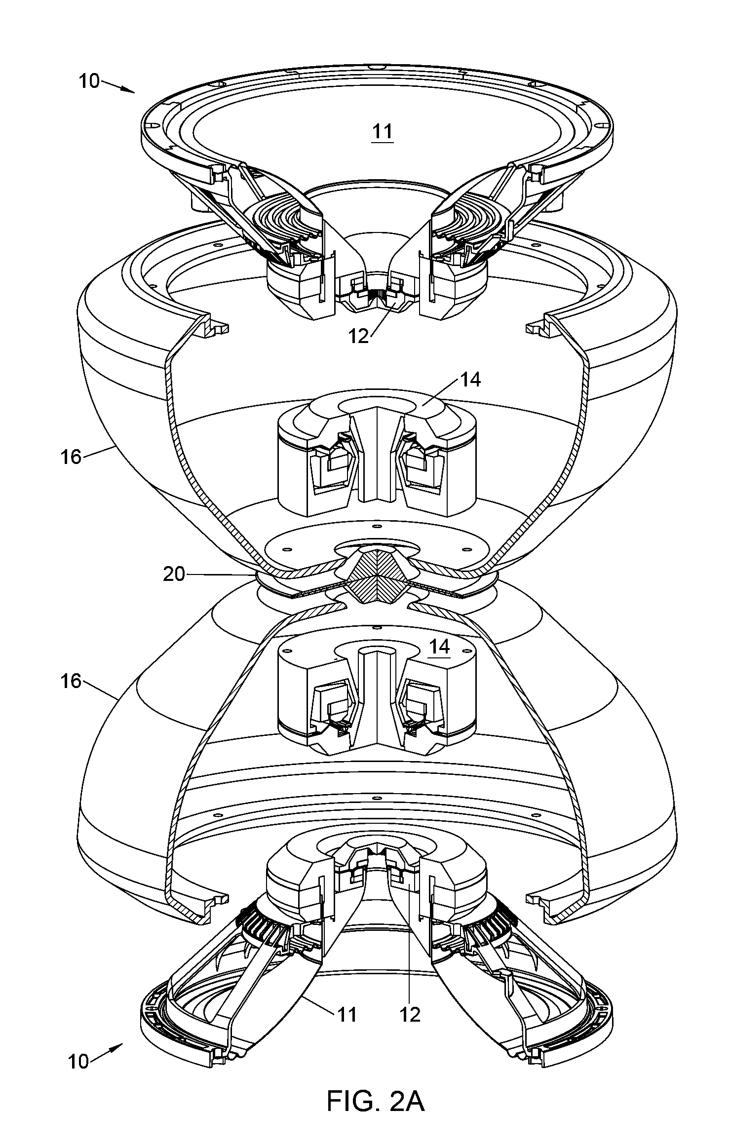
[0040]The embodiment comprises two low-frequency / high-frequency coaxial loudspeakers 10, two mid-high frequency compression drivers 14, and two enclosures 16. The loudspeakers are fixed correspondingly at the larger and the smaller openings of the enclosures 16, together with which they make up two low frequency closed box arrangements of the embodiment. The enclosure necessary wall thickness depends strongly of its material's mechanical properties, and in case of fiber glass composite 6 mm thickness has proved to be fully adequate.

[0041]Enclosure side walls are generated as a surface of revolution with the curvature of the surface being defined in its initial extension by a hyperexponential formula. This initial part, starting from the output of the mid-high frequency compression driver 14, defines together with a circular plate 20 said hyperexponential horn expansion in radial direction. The middle section, being a substantially straight line seg...

second embodiment

DESCRIPTION OF THE SECOND EMBODIMENT

[0049]The second embodiment, being the half of the first embodiment, is illustrated on FIG. 3A as an acoustic measurement sound source, mounted on floor. FIG. 3B illustrates the same embodiment, used for speech and music reinforcement and sound reproduction, mounted on a ceiling. The embodiment comprises one coaxial loudspeaker 10, mounted on enclosure 16, behind which a mid-high frequency compression driver 14 is fixed on a small opening of the enclosure. Mid-high frequency radially expanding horn is obtained between a substantially circular plate 20 mounted on floor 24 or ceiling 28 and enclosure's outer walls in driver's vicinity. Further, the hard floor or ceiling is used as one of the horn flares. Each spherical sound source half, mounted together with the circular plane half on a hard floor, or on any flat hard surface, is operated individually as spherical sound source in so obtained half spherical space. As in the first embodiment, low fre...


PUM


Abstract

Spherical sound source comprising two coaxial loudspeakers and two mid-high frequency compression drivers. Low frequencies are radiated by the two low-frequency sections of the coaxial loudspeakers. Mid-frequencies 500 Hz-2000 Hz are radiated by the two mid-high frequency compression drivers. High-frequencies 2 kHz-10 kHz are radiated in the horizontal plane by the same mid-high frequency arrangement together with two compression drivers of the coaxial loudspeakers in each vertical direction. Identical drivers form three pairs. One driver from each pair is enclosed in one of two symmetrically opposite half-embodiments, spaced at predetermined distance to create a common radially expanding horn for the two mid-high frequency compression drivers. All loudspeakers share the same vertical axis of rotational symmetry. The two half-embodiments might be used as separate standalone spherically radiating sources when installed on hard surface. The invention is appropriate for sine-swept acoustic measurements and sound isolation measurements in high sound transmission class buildings.

Description

PRIOR ART[0001]Omni directional sound sources currently used for acoustic measurements are known as comprising multiple wideband loudspeakers arranged in dodecahedron, semi-dodecahedron, or another multi-hedron arrangements, to our knowledge, up to 120-hedron. Dodecahedron loudspeaker enclosure unit is patented by George W. Siolis, Pat. No. D. 226,567 in 1973. Another example of a dodecahedral speaker system is illustrates in FIG. 1, US Patent 2005 / 0025319 A1 of Iwao Kawakami. These configurations are based on the superposition principle, presuming spreading of infinite number of infinitely small and infinitely wide-band isotropic point sources over a spherical surface in order to obtain spherical radiation. Even though this presumption might be true in the above mentioned case, in reality it is neither feasible nor practical. In practice, a reasonably sized spherical surface would normally accommodate 12 or so membrane loudspeakers, and interference between them starts from mid-fre...

Claims


Application Information

Patent Timeline
Patent Type & Authority Applications(United States)
IPC IPC(8): H04R1/20H04R1/02
CPCH04R1/227H04R1/26H04R1/323
Inventor VALTCHEV, PLAMEN IVANOVDIMITROV, DIMITAR KIRILOV
Owner VALTCHEV PLAMEN IVANOV
Why Eureka
Try Eureka