Heat generating body

a heat-generating body and body technology, applied in the field of heat-generating bodies, can solve the problems of low temperature burn, discomfort of stripping off the skin, and giving an uncomfortable feeling when in use, and achieve the effects of moderate warmth, mild deformation of the mesh-like sheet, and eliminating discomfor

Inactive Publication Date: 2014-01-30
MYCOAL
View PDF5 Cites 15 Cited by
  • Summary
  • Abstract
  • Description
  • Claims
  • Application Information

AI Technical Summary

Benefits of technology

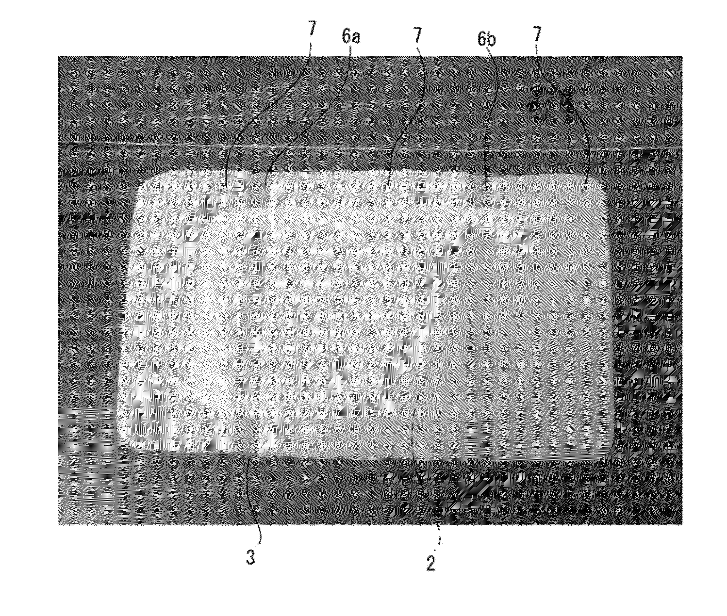
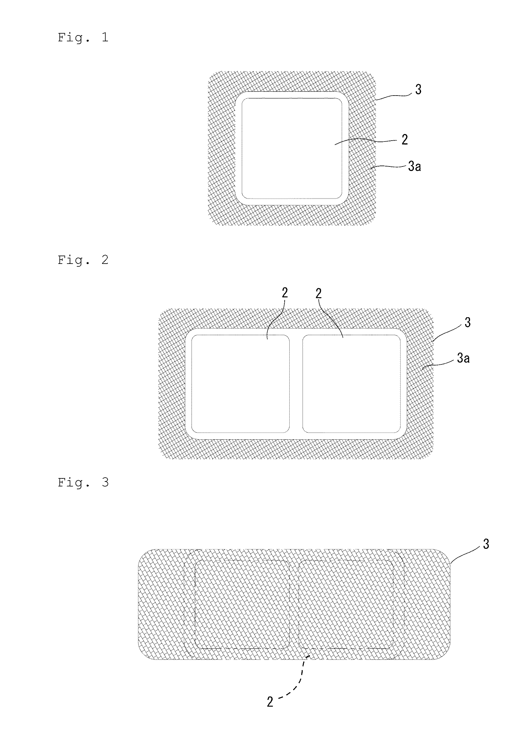
[0025]According to the present invention, the heat generating member of flat shape, sheet-shape, or the like with the wide surface is provided on one face side which is the sticking side of the mesh-like sheet larger than the outer shape of the wide surface of the heat generating member, and an adhesive layer is provided on the mesh-like sheet located on the outer peripheral part of the heat generating member. The heat generating body can thereby be stuck to the skin of the body through the adhesive layer provided on the rear face of the mesh-like sheet extending to the outer periphery of the heat generating member. Since the heat generating member itself is not stuck to the body, even if the mesh-like sheet is deformed following the movement of the body, independence is kept without completely following this deformation to eliminate an uncomfortable feeling when in use. Further, since the heat generating member is not in close contact with the skin through a full-face adhesive, the slight deformation of the mesh-like sheet easily causes in-and-out of air between the heat generating member and the skin to maintain the moderate sense of warmth. As a result, the burden on the skin is relieved when used by a person with a delicate skin or used continuously for many hours, and the low temperature burn can be prevented.
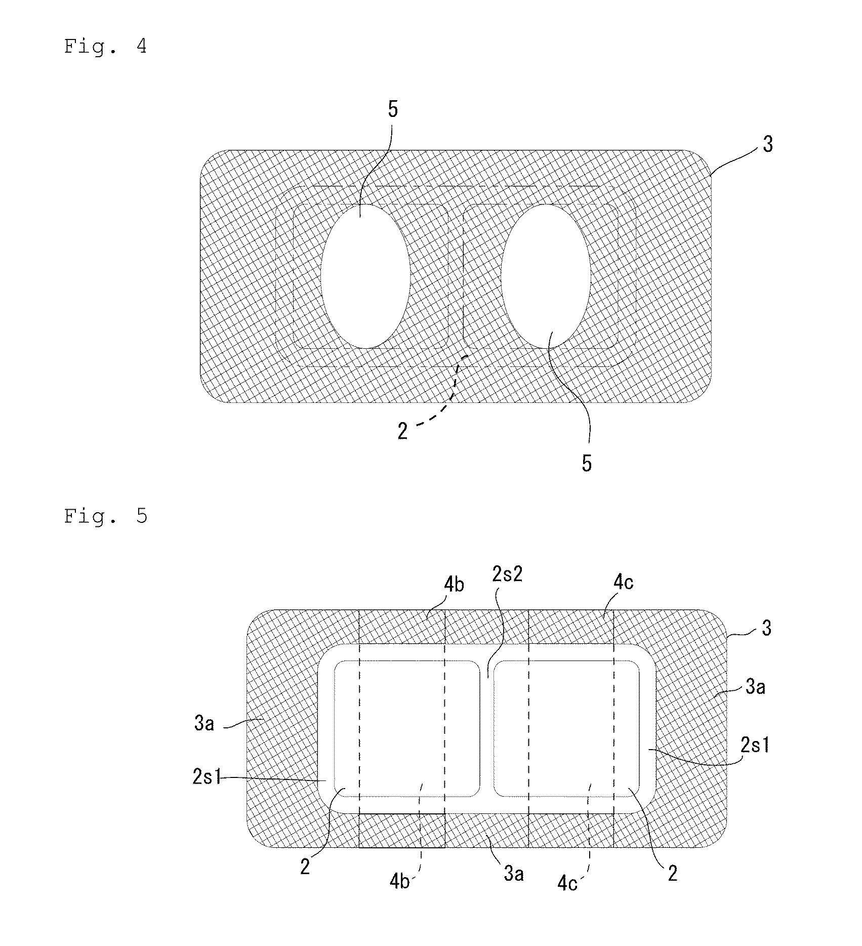
[0026]An air permeability rate and sticking force can be adjusted by providing the mesh-like sheet with holes larger than the average hole diameter of holes provided in the mesh-like sheet. If the holes themselves provided in the mesh-like sheet are uniformly provided, the air permeability rate and sticking force become uniform, but the air permeability rate and sticking force can be adjusted by the optionally selected hole size. On the other hand, if the hole diameters are made different between the longitudinal center part and both ends or the like of the heat generating body, the temperature of the heat generating body can be uniformed as a whole, for instance. Further the sticking force, applied to the skin of the body, of the adhesive layer provided on the rear face of the mesh-like sheet located at the outer peripheral part of the heat generating member can be suitably adjusted.
[0027]The size of the heat generating member can be suitably changed by forming the adhesive layer on the whole rear face of the mesh-like sheet and sticking the heat generating member to the mesh-like sheet through the adhesive layer. The heat generating body can thereby be made corresponding to an applied part of the body.
[0028]The adhesive layer is formed within a range of 10 to 80% of the surface area of a region, in which the heat generating member is located, on the mesh-like sheet (excluding a seal part if the seal part is formed at the peripheral edge of the wide surface of the heat generating member), and adhesive layers of the predetermined width are formed at predetermined spaces at the seal part of the heat generating member extending in the orthogonal direction to the longitudinal direction of the heat generating body. An air permeability rate enough to obtain the sufficient sense of warmth as the heat generating body can thereby be obtained, and simultaneously the heat generating member can be firmly stuck to the mesh-like sheet so as not to fall off. The region may be based on heat generation characteristics requested at the body applied part or the like of the heat generating body and does not necessarily need to have a high or low air permeability rate. However, since the adhesive layers of the predetermined area ratio are provided, sticking between the mesh-like sheet and the heat generating member can be made firm according to the magnitude of movement of the applied part.
[0029]In the case of the heat generating body having a plurality of heat generating members at least in the longitudinal direction of the heat generating body or also in the orthogonal direction to the longitudinal direction, the region surrounded by the heat generating members located at the outermost peripheral edge is made the region, in which the heat generating members are located, on the mesh-like sheet (excluding the seal parts of the heat generating members located at both ends in the longitudinal direction of the heat generating body in the region). The heat generating body can thereby be conformed to the shape of the applied part of the body, and further as the heat generating member, the heat generating body of equal temperature on the whole can be obtained.
[0030]In the region, in which the heat generating member is located, on the mesh-like sheet, the non-adhesive sections without the adhesive layer are connectedly formed also on the mesh-like sheet while adjusting the width of the non-adhesive sections in the direction orthogonal to the longitudinal direction of the heat generating body. One length of the adhesive provided particularly at the long side of the orthogonal direction to the longitudinal direction of the heat generating body can be shortened, and when the heat generating body is stuck to the skin of the body, a force caused by the movement to deform the heat generating body is dispersed to obtain the heat generating body that relieves an uncomfortable feeling.

Problems solved by technology

However, this conventional heat generating body is used stuck to the skin through the adhesive layer formed on the rear face, it has a problem of giving an uncomfortable feeling when in use because the heat generating body formed with the adhesive layer is not deformed following the movement of the body.
In the case of using the heat generating body for a long time, there have been also a problem of causing a low temperature burn because the adhesive layer of the heat generating member continues to be in close contact with the skin of the body, and inconvenience of stripping off the skin in the case of trying to strip off the heat generating body together with the adhesive layer when causing the low temperature burn.

Method used


Image

  • Heat generating body
  • Heat generating body
  • Heat generating body

Examples


example 1

[0143]The heat generating composition was placed on a base material formed by laminating polyethylene 70 mm long, 75 mm wide and 40 μm thick on a nylon nonwoven fabric (weight per unit area of 40 g / m2) 70 mm long and 75 mm wide, and the top of the heat generating composition was covered with a covering material formed by laminating a porous film of polyethylene 100 mm long, 115 mm wide and 70 thick on a mesh-like nonwoven fabric (weight per unit area of 40 g / m2) 100 mm long and 115 mm wide. The base material and the covering material were sealed at the peripheral edge of the heat generating composition to form a heat generating member. An adhesive composed of an acrylic solvent-based adhesive was applied (an applied thickness of 23 μm) onto the covering material outside of the seal to form a heat generating body in Example 1.

example 2

[0144]protective sheet 80 mm long, 85 mm wide and 0.38 mm thick was provided on the heat generating member of the heat generating body in Example 1 to form a heat generating body in Example 2.

[0145]The protective sheet in use is structured to laminate a polyethylene film with a thickness of 28 μm on a metallocene polyethylene film with a thickness of 12 μm and to apply an acrylic adhesive thereon with an applied amount of 6±1 g / m2 to laminate a nonwoven fabric with 100% rayon with a weight per unit area of 55±5 g / m2, and the protective sheet was provided on the heat generating member so that the nonwoven fabric was located on the sensor side of a tester.

[0146]Temperature was measured under the following measuring conditions.

[Temperature Measuring Test of the Heat Generating Part]

(A) Testing Condition

[0147]Environmental temperature: 20±1.5° C.

[0148]Placing table: a heater having a hose connecting part for circulating warm water with a height of 100 mm (a volume of 16.42 L) was placed...

example 3

[0156]An explanation is made on an example of changing the weight per unit area and material of the nonwoven fabric to inspect the effectiveness of the protective sheet.

[0157]A heat generating composition was placed on a base material formed by laminating a polyethylene resin film with a thickness of 40 μm on a rayon spunlace nonwoven fabric (weight per unit area of 45 g / m2) 70 mom long and 75 mm wide, and the top of the heat generating composition was covered with a covering material formed by laminating a porous film made of polyethylene resin with a thickness of 70 μm, on a PET spunlace nonwoven fabric (weight per unit area of 30 g / m2) 70 mm long and 75 mm wide. The base material and the covering material were then sealed at the peripheral edge of the heat generating composition to form a heat generating member. An adhesive (23 μm in applied thickness) formed of an acrylic solvent-based adhesive was applied to a mesh-like sheet (weight per unit area of 40 g / m2) made of a PET spun...


PUM


Abstract

An object of the present invention is to provide a heat generating body giving no uncomfortable feeling when in use and causing no direct close contact between a heat generating member and the skin by an adhesive to relieve the burden of the skin while eliminating a low temperature burn even for a person with a delicate skin and in the case of continuous use. The heat generating body of the present invention is characterized in that the heat generating member having a wide surface is provided on a mesh-like sheet larger in outer shape than the one-side wide surface of the heat generating member and that an adhesive layer is provided on the mesh-like sheet located at the outer peripheral part of the heat generating member.

Description

TECHNICAL FIELD[0001]The present invention relates to a heat generating body that has a heat generating member composed to generate heat by a heat generating composition such as iron powder and that is used directly stuck to the skin of the body.BACKGROUND ART[0002]The conventionally known heat generating body of this kind is, as shown in Patent Document 1, used stuck to the skin utilizing an adhesive layer formed on the rear face, which is the sticking side to the body, of a heat generating member.[0003]However, this conventional heat generating body is used stuck to the skin through the adhesive layer formed on the rear face, it has a problem of giving an uncomfortable feeling when in use because the heat generating body formed with the adhesive layer is not deformed following the movement of the body. In the case of using the heat generating body for a long time, there have been also a problem of causing a low temperature burn because the adhesive layer of the heat generating mem...

Claims


Application Information

Patent Timeline
Patent Type & Authority Applications(United States)
IPC IPC(8): A61F7/03A61M5/44
CPCA61M5/44A61F7/03A61F2007/0226A61F7/034A61F2007/0257A61F2007/0258
Inventor USUI, YASUMASA
Owner MYCOAL
Why Eureka
Try Eureka