
Surgical reduction clamp

Active Publication Date: 2014-01-30
STRYKER EURO OPERATIONS HLDG LLC
View PDF5 Cites 18 Cited by
  • Summary
  • Abstract
  • Description
  • Claims
  • Application Information

AI Technical Summary

Benefits of technology

The invention is a surgical reduction clamp that is easy to use and handle. It includes a ratchet toothed member that can be engaged with the other clamping arm to securely lock the position of the arms. This member prevents the arm from slipping out of the teeth it engages with. Overall, the clamp is designed to improve usability and facilitate surgical procedures.

Problems solved by technology

Many of them are limited in their practical applicability for certain surgical treatments due to insufficient usability characteristics from the perspective of the operating surgeon.
However, such instruments are still not applicable in many surgical situations and usability aspects may still be improved.

Method used


Image

  • Surgical reduction clamp
  • Surgical reduction clamp
  • Surgical reduction clamp

Examples


Embodiment Construction

[0027]In the following, various embodiments of a surgical reduction clamp will be described. The same reference numerals will be used to denote the same or similar structural features.

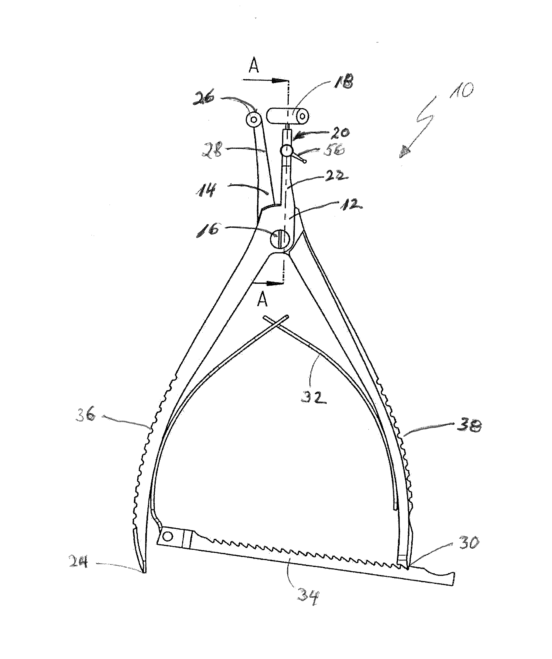
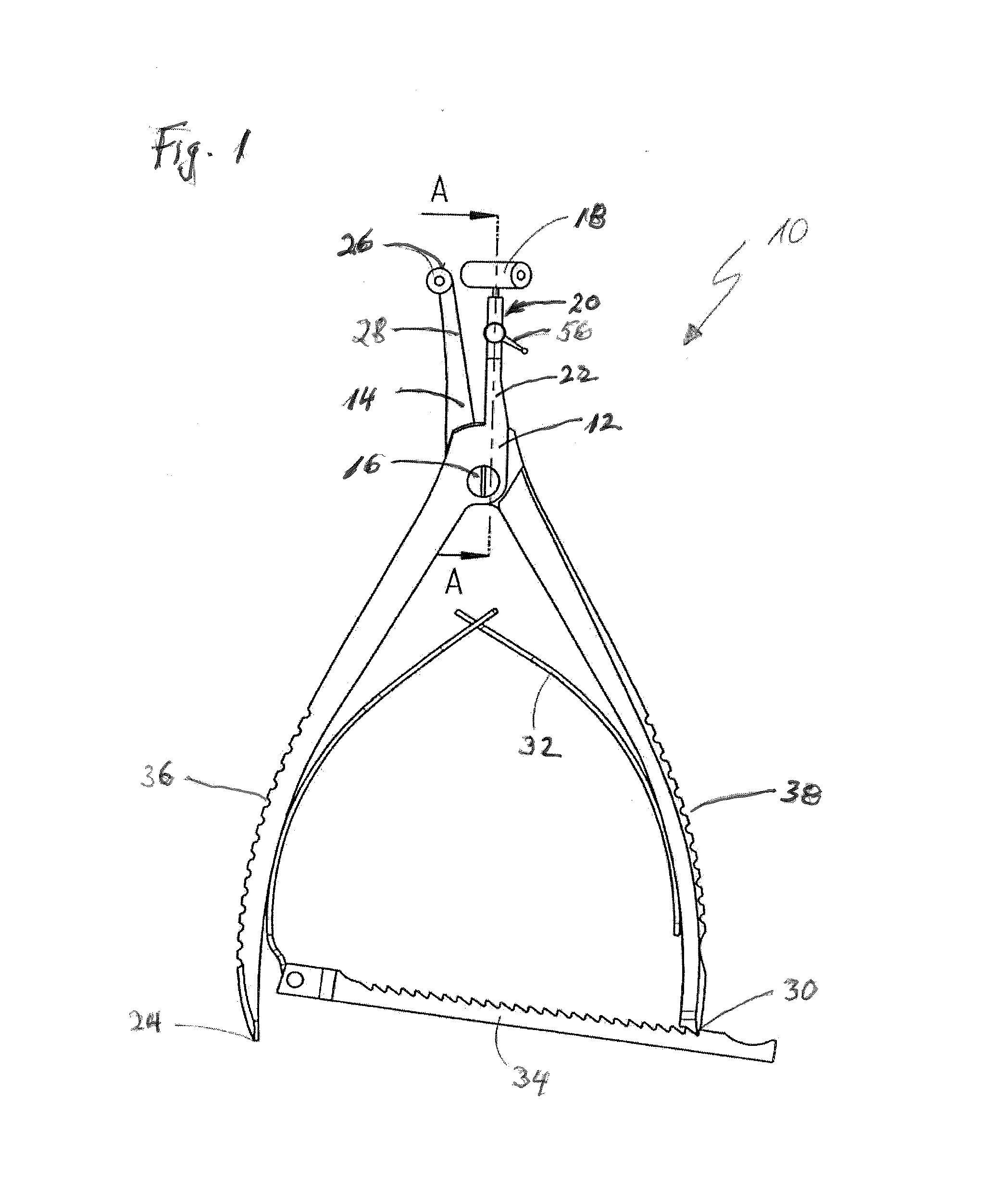
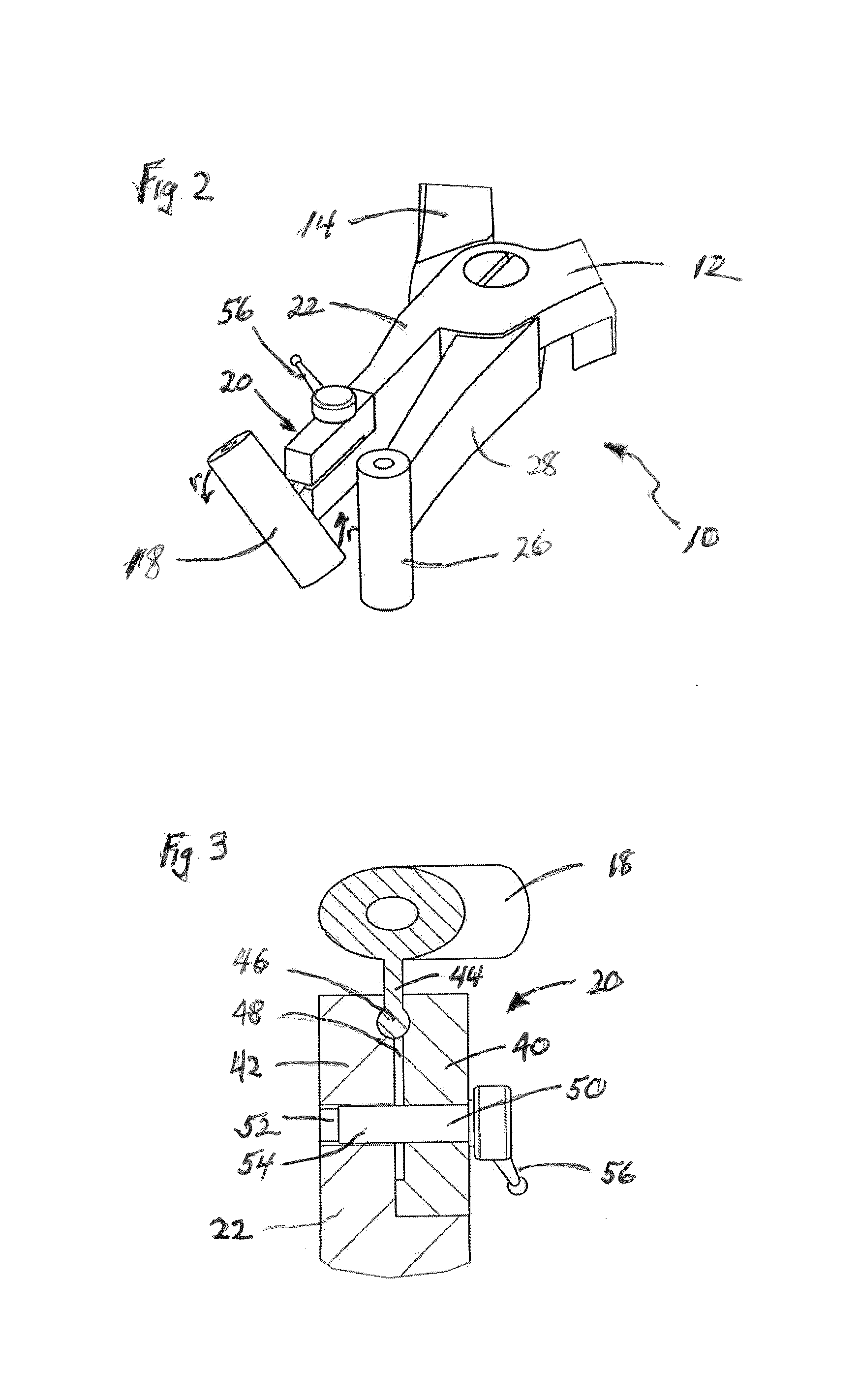
[0028]FIG. 1 shows a side view of an embodiment of a surgical reduction clamp 10. The reduction clamp 10 comprises a first clamping arm 12 and a second clamping arm 14 which are pivotably coupled to one another by a screw or bolt member 16. The first clamping arm 12 includes a tip portion 18 forming its proximal end. In FIG. 1, the tip portion 18 is formed as a sleeve for accommodating a surgical wire, such as a k-wire. The tip portion 18 is coupled to a joint 20 and the joint 20, in turn, adjoins a base portion 22 of the first clamping arm 12 which extends to the distal end 24 thereof.

[0029]As opposed to the first clamping arm 12, the second clamping arm 14 does not include a joint. The second clamping arm 14 only includes a tip portion 26 forming its proximal end and a base portion 28 integrally adjo...


PUM


Abstract

A surgical reduction clamp has a first clamping arm and a second clamping arm movable relative to the first clamping arm. The first clamping arm comprises a base portion, a tip portion, a joint movably coupling the tip portion to the base portion, and a locking member adapted to lock the joint so as to fasten a position of the tip portion relative to the base portion. The joint is a revolute joint having a spherical portion which can be locked into position by a clamping force.

Description

CROSS-REFERENCE TO RELATED APPLICATION[0001]The present application claims priority from European Patent Application No. 12 005 423.4 filed Jul. 25, 2012, the disclosure of which is hereby incorporated herein by reference.BACKGROUND OF THE INVENTION[0002]The present disclosure generally relates to the field of surgical instruments. In particular, a surgical reduction clamp is described.[0003]When treating a bone fracture, bone fragments are typically aligned in a first step. The act of aligning and restoring the correct position of bone fragments is called reduction. Perfect anatomical reduction reverses the mechanism of injury which originally created the fracture displacement.[0004]In a surgical procedure, often a screw, plate, pin or wire is installed across a fracture in order to maintain the alignment of the bone fragments for the later adhesion process. During the installation procedure, it is in many cases important to clamp the bone fragments together so as to eliminate the ...

Claims


Application Information

Patent Timeline
IPC IPC(8): A61B17/68
CPCA61B17/68A61B17/8866A61B17/2804A61B17/2816A61B17/282A61B2017/00407A61B2017/00473A61B2017/0069A61B2017/2837
Inventor SCHMUCK, MANFREDDIGESER, DENISKOERNER, UWE
Owner STRYKER EURO OPERATIONS HLDG LLC
Features
  • Generate Ideas
  • Intellectual Property
  • Life Sciences
  • Materials
  • Tech Scout
  • Unparalleled Data Quality
  • Higher Quality Content
  • 60% Fewer Hallucinations
Learn More