Integral Multiple Stage Safety Valves

a safety valve and multiple stage technology, applied in the field of multiple safety valves, can solve the problems of high cost, high manufacturing cost, and complicated design of valves, and achieve the effects of eliminating turbulence and pressure drop, high reliability, and simple manufacturing

Active Publication Date: 2014-02-06
TEJAS RES & ENG
View PDF9 Cites 13 Cited by
  • Summary
  • Abstract
  • Description
  • Claims
  • Application Information

AI Technical Summary

Benefits of technology

[0006]The invention disclosed and claimed in this application is for subsurface multiple stage safety valves that are highly reliable, compact, simple to manufacture and include at least two complete, separately functioning safety valves. In accordance with another aspect of the invention, dual control lines are provided which allows for individual operation of each safety valve. This allows the operator the option of operating one valve and keeping the other as a stand-by or operating both valves simultaneously. The principles of the invention can be applied to pressure equalizing or non-pressure equalizing closing systems. Due to the internal design of the valve, the internal flow path is substantially of uniform diameter thus eliminating turbulence and pressure drops due to internal obstructions and irregularities. Furthermore the exterior diameter of the tool is substantially constant. The tool includes a minimum of body joints which increases the reliability of the tool and simplifies construction.
[0007]Another advantage of the valve is the reduction of body joints necessary for its construction. Reducing the number of body joints reduces potential leak paths of hydrocarbons from the inside. Fewer joints also reduces the cost of the body joint.

Problems solved by technology

These valves are complicated in design and are not compact as is critical in the art.
Furthermore the internal flow passage for the fluids are not of a single diameter and many contain obstruction shoulders or changes in diameter that result in turbulent flow or pressure drops.
During design qualification of subsurface safety valves, a body joint must be designed qualified and verified which is an expensive process, because of the consequences of a leak in a valve of this type.

Method used


Image

  • Integral Multiple Stage Safety Valves
  • Integral Multiple Stage Safety Valves
  • Integral Multiple Stage Safety Valves

Examples


Embodiment Construction

[0016]Initially, in order to better understand the invention, the prior art will be discussed. Currently in order to provide redundancy, two valves are simply joined together by a pup joint. The upper valve is connected to production tubing by a threaded connection and the lower valve is connected to lower production tubing by a threaded connection. This results in six body joints. As discussed above these body joints increase the likelihood of leak passages and increase the cost of fabrication.

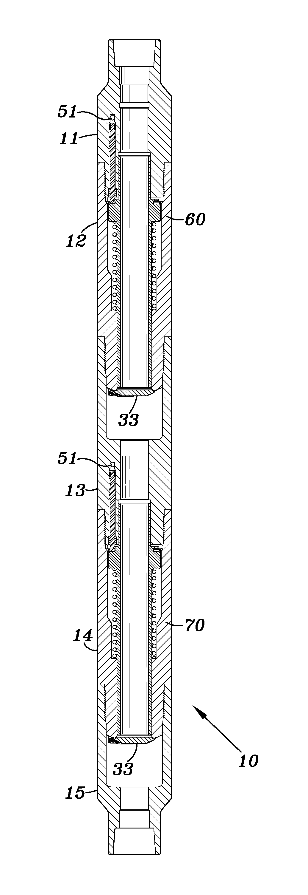
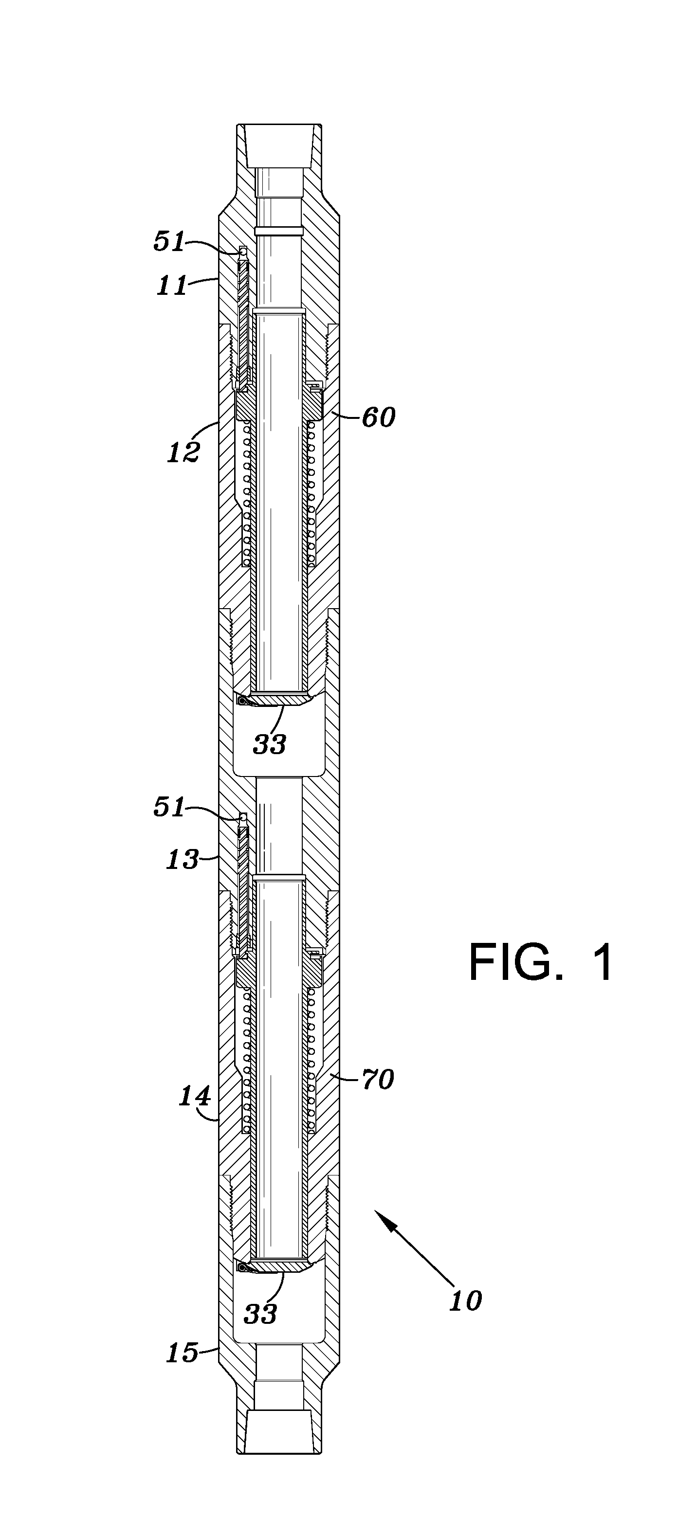
[0017]Referring to FIG. 1, an embodiment of the present invention is illustrated. The integral multiple stage safety valve includes five tubular sections 11, 12, 13, 14 and 15 connected to each other by any suitable known methods such as internal and external threads. Upper connection body 11 may be connected to any tubular to be placed within the well. A first spring housing 12 is connected at one end to the upper connection body and at the other end to an integral chamber housing 13 which i...


PUM


Abstract

An integral multistage safety valve is designed to provide a second level of protection should a first stage fail. The valve may be used in oil and / or gas wells. The interior portion of the multiphase safety valve is designed so as to reduce turbulence and pressure loss through the valve when the valve is in an open position. The valves may be independently operable, or operable with a single control line. The multi-stage valve reduces the number of body joints required to construct two identical valves thereby reducing cost and potential leak paths and increasing reliability of the system.

Description

BACKGROUND OF INVENTION[0001]1. Field of the Invention[0002]This invention is for multiple safety valves for location within an oil or gas well that can be activated to open or close and thus prevent, or permit upward flow of fluids within the well for example in case of an emergency.[0003]2. Description of Related Art[0004]Downhole safety valves are known that include a housing, a flapper valve and a remotely controlled actuator for closing the normally open valve in case of an emergency. See for example U.S. Pat. No. 7,392,849. Also serially arranged valves in a downhole tool are also known. Examples of such are shown in U.S. Pat. Nos. 6,394,187; 7,673,689; 4,846,281; 4,605,070; and 6,152,229. These valves are complicated in design and are not compact as is critical in the art. Furthermore the internal flow passage for the fluids are not of a single diameter and many contain obstruction shoulders or changes in diameter that result in turbulent flow or pressure drops.[0005]Threaded...

Claims


Application Information

Patent Timeline
Patent Type & Authority Applications(United States)
IPC IPC(8): E21B34/06
CPCE21B34/10E21B2200/05E21B34/12
Inventor JANCHA, ROBERT A.HILL, JR., THOMAS G.
Owner TEJAS RES & ENG
Why Eureka
Try Eureka