Filter manufacturing machine, filter manufacturing method using the machine, and hollow filter

Active Publication Date: 2014-02-06
JAPAN TOBACCO INC
View PDF3 Cites 18 Cited by
  • Summary
  • Abstract
  • Description
  • Claims
  • Application Information

AI Technical Summary

Benefits of technology

[0017]According to the present invention, the mandrel has the small-diameter portion located at the inlet of the forming tube, the large-diameter portion located at the outlet of the forming tube, and the diameter expansion portion located between the small- and large-diameter portions. The diameter expansion portion is located downstream of the heat treating section as viewed in the moving direction of the filter tow. The filter tow is lumped by the heat treating section and has its outer shape formed by the tubular forming path of the forming tube, and the through hole is formed by the mandrel. That is, the through hole is formed around the outer shape of the mandrel. Then, as the filter tow further advances through the tubular forming path, the diameter of the through hole is enlarged by the diameter expansion portion. This makes it possible to obtain a filter of which the tow does not project into the through hole from its surface and which thus has good appearance. Also, the adhesion of fibers forming the filter tow improves. Further, since

Problems solved by technology

It is, however, often the case that the tow projects inward from the surface defining the through hole, and a filter rod with such a through hole is regarded as low in quality and rejected as a defective article.
Also, if the surface region of the filter rod around the through hole is not satisfactorily high in hardness, the through hole is crushed when the filter rod is cut in a subsequent process, leading to lowering of the quality.
If the plasticizer is used in a large amount, however, a problem arises in that the filter itself is dissolved or gives off an offensive smell.
Since the mandrel has an outer shape with the same diameter an

Method used


Image

  • Filter manufacturing machine, filter manufacturing method using the machine, and hollow filter
  • Filter manufacturing machine, filter manufacturing method using the machine, and hollow filter
  • Filter manufacturing machine, filter manufacturing method using the machine, and hollow filter

Examples


Embodiment Construction

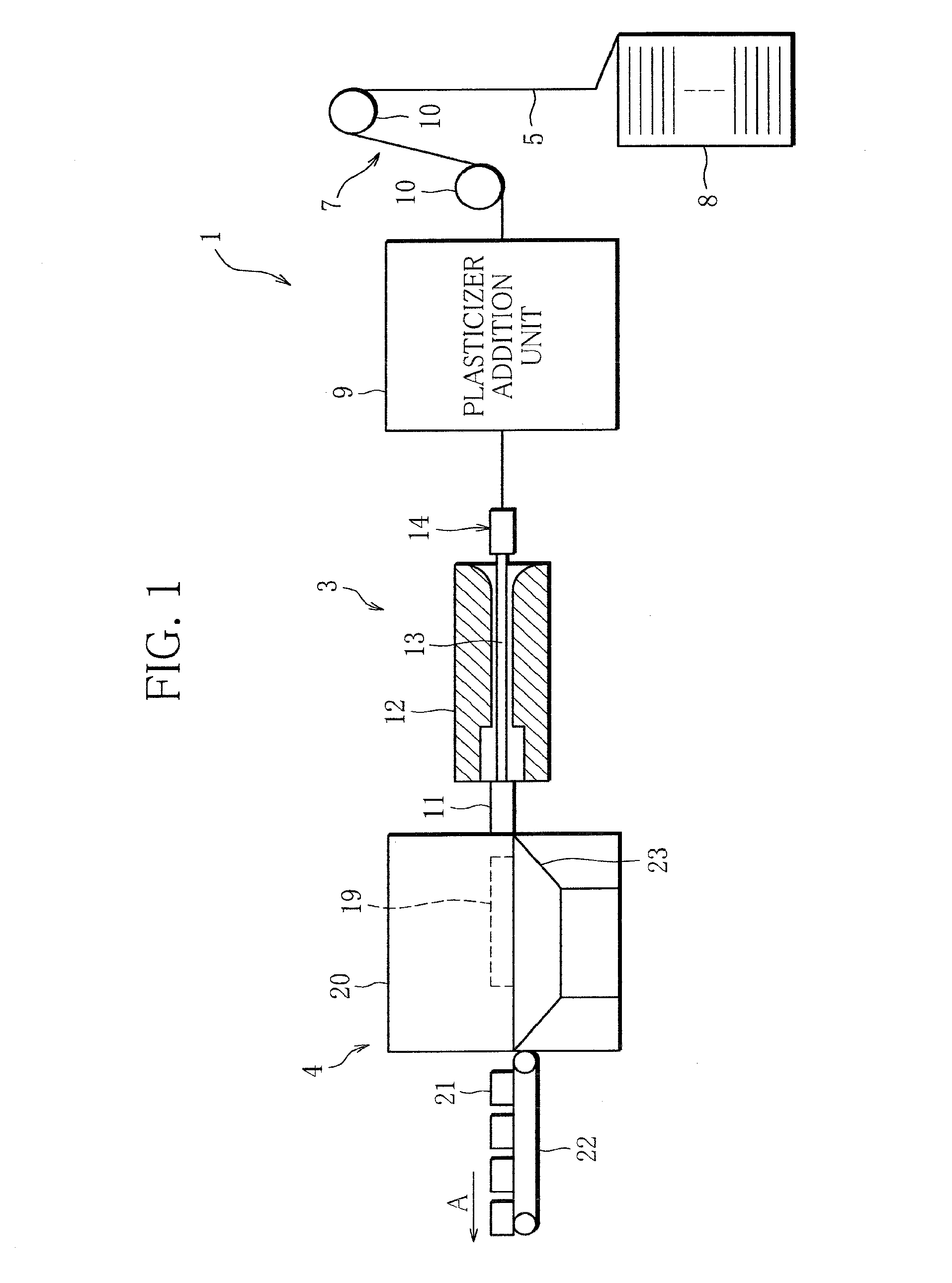
[0027]A filter manufacturing machine 1 illustrated in FIG. 1 includes a feed path 7, a forming device 3, and a wrapping device 4. The feed path 7 is a path along which filter tow (fibers) 5 is continuously fed. A storage vessel 8 storing the filter tow 5 such as cellulose acetate fibers is arranged at the head end of the feed path 7. The feed path 7 has a plurality of (in the figure, two) guide rollers 10 and is connected to the forming device 3, described in detail later. Also, the feed path 7 is provided with a plasticizer addition unit 9. The plasticizer addition unit 9 is equipped with a conventionally known banding jet, a pair of pretension rollers, a pair of brooming rollers and the like (none of which is shown), and the filter tow 5 is first bloomed by these elements. Further, the plasticizer addition unit 9 is provided with a conventionally known sprayer (not shown) for adding a plasticizer to the tow 5. As a result, the tow 5 is hardened to some extent.

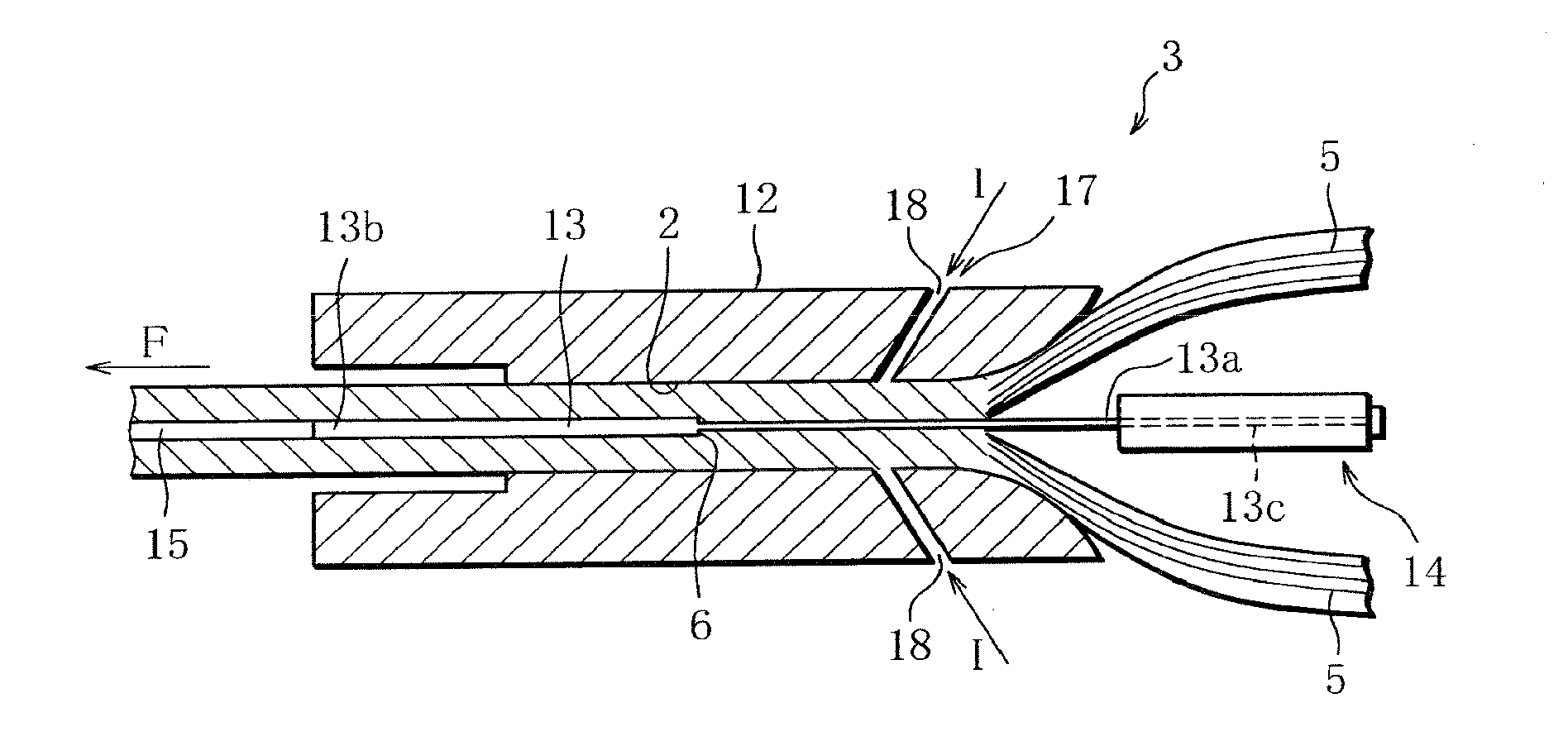
[0028]The forming dev...


PUM

PropertyMeasurementUnit
Diameteraaaaaaaaaa
Densityaaaaaaaaaa

Abstract

A filter manufacturing machine includes a forming device for forming filter tow into a hollow rod-shaped continuous filter body, a forming tube included in the forming device and having a tubular forming path through which the filter tow is passed while being brought together, a mandrel arranged in the forming tube and forming the tubular forming path in cooperation with the forming tube, and a heat treating section included in the forming tube and configured to heat the filter tow while the filter tow passes through the tubular forming path. The mandrel has a small-diameter portion located at the inlet of the forming tube, a large-diameter portion located at the outlet of the forming tube, and a diameter expansion portion located between the small- and large-diameter portions. The diameter expansion portion is located downstream of the heat treating section as viewed in the moving direction of the filter tow.

Description

TECHNICAL FIELD[0001]The present invention relates to a filter manufacturing machine for making hollow filters from filter fibers, a filter manufacturing method using the machine, and hollow filters.BACKGROUND ART[0002]Conventional filter manufacturing machines include a storage vessel storing, for example, acetate tow for use as filter fibers, and the tow (filter fibers) is fed from the storage vessel along a predetermined feed path. In the process of feeding, the tow is bloomed. Subsequently, a plasticizer such as triacetin is added to the tow, and the tow is supplied to a rod forming device. In the rod forming device, the tow is formed into a rod, and the rod-shaped tow is wrapped in paper to continuously form a filter rod.[0003]The tow is formed into a rod by means of a section called forming tube. While passing through the forming tube, the tow is compressed and formed into a rod. There has also been known a technique whereby the tow is formed into a rod and at the same time a ...

Claims


Application Information

Patent Timeline
IPC IPC(8): B31D5/00B01D39/14
CPCB01D39/14B31D5/0082A24D3/0233A24D3/0279
Inventor TORAI, HIROYUKINAKAMURA, SATOSHI
Owner JAPAN TOBACCO INC
Why Eureka
Try Eureka