Contact lens manufacturing method

a manufacturing method and contact lens technology, applied in the field of contact lens, contact lens manufacturing and contact lens packaging, can solve the problems of user discomfort, inconvenient cutting, and high cost of vial packaging, and achieve the effects of enhancing the efficiency in the use of procedures and materials, efficient manufacturing process, and efficient manufacturing and distribution

Active Publication Date: 2014-02-06
DAYSOFT
View PDF5 Cites 15 Cited by
  • Summary
  • Abstract
  • Description
  • Claims
  • Application Information

AI Technical Summary

Benefits of technology

[0039]The method and articles of the present invention enable a significantly more efficient manufacturing process for contact lenses and in particular packaged daily disposable contact lenses. The methods and articles of the invention enable a contact lens mould half to be utilized as a blister cup in contact lens packaging whilst enhancing the efficiency in terms of procedure and material use in packaged contact lens manufacture. The method and articles of the invention further enable the use of a contact lens mould half as a packaged contact lens blister cup which packaged contact lens blister cup remains compact, efficient to manufacture and distribute and reduces handling of the manufactured contact lens.
[0040]The method of designing and manufacturing contact lenses according to further aspects of the present invention, taking advantage of the unconstrained manner in which the mould halves engage (e.g. ball and socket arrangement) is significantly more efficient and negates the need for precision manufacture of peripheral portions of the mould halves (as compared with prior art piston-cylinder arrangements) and allows relatively straightforward accommodation in changes in the manufacture process (e.g. different materials or conditions).

Problems solved by technology

For example, the cost of vial packaging renders this system inappropriate on cost grounds for any frequent replacement modality of lens wear.
If the edge-formation is inconsistent, it may require cutting.
If the edge formed is too discrete, it may cause discomfort for the user.
A further problem in the cast-moulding of contact lenses is how to deal with monomer ‘shrinkage’, the inevitable reduction in volume in the curing stage.
Failure to properly compensate for this shrinkage will result in unacceptably high wastage rates and / or poor quality products containing voids or bubbles.
A particular problem with this method, however, is that fluid within the channel (at the edges of the mould cavity), where fluid from the reservoir is intended to flow into the mould cavity during curing, tends to cure more rapidly (due to the confined volume) as compared with the main body of the lens cavity.
A further problem is that post-curing, it is necessary to cut the cured ‘reservoir’ ring from the mould, or where it is selectively cured to cut or polish imperfectly formed edges.
A particular disadvantage of this system is that the diaphragm portion which flexes during curing is difficult to form in a manner which gives consistent curvature in the lenses (or to ensure that cavitation and bubbles in the lens are avoided).
Further, in providing a return on a non-flexible shoulder, removal of the lens from the female mould half is difficult, even if hydrated in situ.
The proposed mould arrangement is bulky (in order to ensure that a slide fit engagement can be achieved and to provide internal volume for later processing), which leads to significant material loss (in the male half that is disposed of) and resultant bulky packaging of contact lens.
Disadvantages of this system include the precision of manufacture necessary to ensure sealed sliding fit and diaphragm behaviour, the increased complexity of requiring superatmospheric pressure, the excess material required to provide the slide-fit engagement (and non-optical) portions of the mould half and the fact that the convention in contact lens use is for the user to be presented with a lens concave surface up.
A particular disadvantage of the flexible lip arrangement is that the flexible lip can affect the seal resulting in reject lenses and the edge portions of resulting lenses tend to be inconsistent and in need cutting or polishing.
The prior art thus suffers from disadvantages mentioned, which typically include one or more of inconsistency of lens edge-forming, reliability and consistency of lens curvature, complexity of manufacturing, requirements for precision in non-optical portions of mould-halves, degree of material waste and unsuitability for use of the lens-forming mould half in packaging.

Method used


Image

  • Contact lens manufacturing method
  • Contact lens manufacturing method
  • Contact lens manufacturing method

Examples


example

Example 1

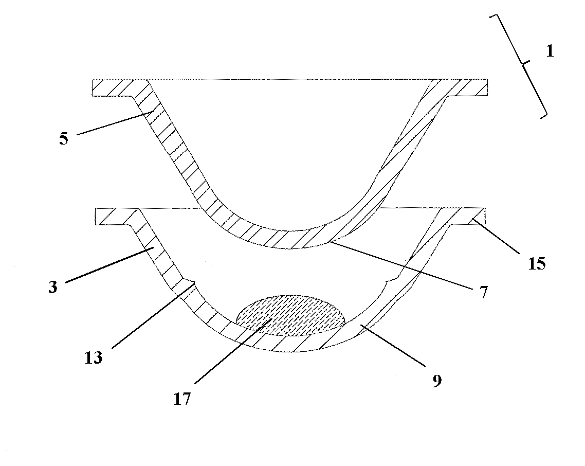
[0120]A pre-hydrated contact lens is formed using the method of the present invention by disposing a quantity of lens-forming composition (comprising hydroxyethyl methacrylate and vinyl pyrrolidone) in a lens-forming cavity formed between male and female mould halves (of polypropylene) of the invention, in accordance with FIG. 1, and thermally curing the composition. The diameters of the pre-cure mould cavity, post-cure mould cavity and dry lens formed were recorded and are presented in Table 1.

TABLE 1Pre-cure mouldPost-cure mouldcavity diameter / cavity diameter / Pre-hydrated lensMoulding No.mmmmdiameter / mm110.587910.551810.553210.595410.49610.517310.565810.522210.527410.584610.54910.549510.586410.507810.54610.562610.4910.53Mean10.580510.519510.5360STDEV0.01320.02640.0138

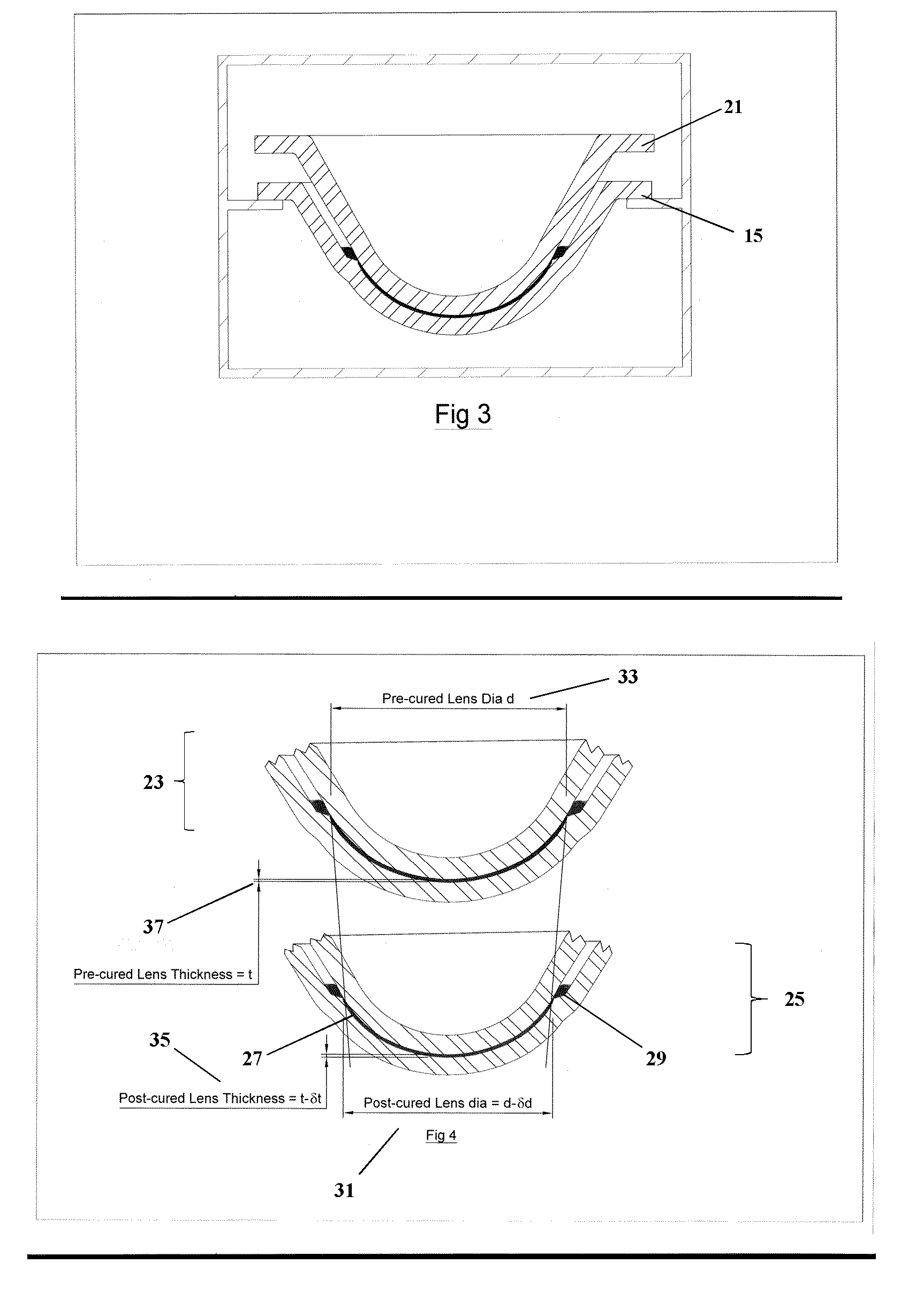
[0121]The mean change in diameter of mould cavity is a 60 μm reduction, which is a 0.58% contraction on a 10.58 mm aperture. This resulted in approximately 10% volume reduction.

[0122]The free and flexible mou...

example 2

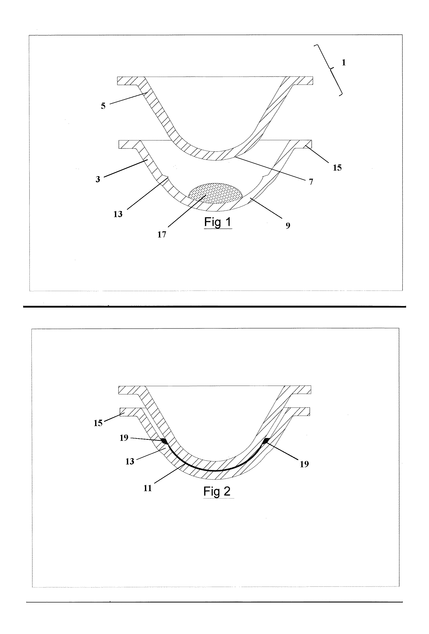
[0123]As discussed above, a particular characterization of the manufacturing method, the female mould half 3 and the blister 59 of the present invention is the flexibility of at least the female mould half to lateral flexibility or radial extension. It is preferable that at least the female mould half it is sufficiently flexible that a return may be configured in the optical surface of the female mould half, associated with the annular ridge, whilst enabling the cured pre-hydrated lens to be released.

[0124]The following sets out the deformation under varying loads for a female mould half formed according to a preferred embodiment of the present invention.

[0125]A female mould half according to a preferred embodiment was placed between fixed and moving platens. Force was therefore applied equally in one direction against the narrow collar 15 of the mould half 3 and in the other direction against the external surface of the domed optical zone 43 of the mould half 3.

[0126]When compressi...


PUM

PropertyMeasurementUnit
diameteraaaaaaaaaa
forceaaaaaaaaaa
diameteraaaaaaaaaa

Abstract

In manufacturing a contact lens, a contact lens mould arrangement in which the engagement between the mould halves is unconstrained and at least one mould half is sufficiently pliable or flexible that during the curing of the contact lens composition at one mold half may move or flex relative to the other to define a post-cure mould cavity of smaller volume than the pre-cure mould cavity and during which the curvatures of the first and / or second mould surfaces are allowed to change provides a significantly more efficient manufacturing process and enables one mould half to be readily utilized as a blister cup for contact lens packaging.

Description

FIELD OF THE INVENTION[0001]This invention pertains generally to the field of contact lenses, contact lens manufacturing and contact lens packaging. It further relates to an apparatus, system and method for the manufacture of contact lenses, to a contact lens and to packaged contact lens and to a method of packaging a contact lens.BACKGROUND OF THE INVENTION[0002]Three basic manufacturing techniques are used in the manufacture of soft contact lenses. These are generally referred to as lathing (cutting both lens surfaces and edge on a pre-polymerised ‘button’), spin casting (using a single concave mould piece to form the front surface of the lens) and cast moulding (using a concave mould piece to form the front surface of the lens and a second convex mould pieces to form the back surface of the lens).[0003]Lathing is a suitable process where there is a low batch size and a wide variety of lens powers and / or shapes required e.g. for toric lens manufacture. Spin casting is a suitable p...

Claims


Application Information

Patent Timeline
Patent Type & Authority Applications(United States)
IPC IPC(8): B29D11/00
CPCB29D11/00038B29D11/00567B29D11/00221B29C39/40B29D11/00057B29D11/00192
Inventor HAMILTON, RONALD
Owner DAYSOFT
Why Eureka
Try Eureka