Vehicular lamp

a technology of vehicle lamps and reflectors, which is applied in the field of vehicle lamps, can solve the problems of poor flexibility in controlling the reflection light of the reflective elements, and achieve the effects of easy adjustment, easy control, and increased flexibility in controlling the reflection

Inactive Publication Date: 2014-02-06
KOITO MFG CO LTD
View PDF3 Cites 25 Cited by
  • Summary
  • Abstract
  • Description
  • Claims
  • Application Information

AI Technical Summary

Benefits of technology

[0009]One or more embodiments of the present invention provides a vehicular lamp including a light guide, which can increase flexibility in controlling reflected light by a plurality of reflective elements formed on a rear surface portion of the light guide.
[0015]As shown in the above configuration, a vehicular lamp according to one or more embodiments of the present invention is configured so that the light of the light source, which is incident on the light guide placed to extend in the predetermined direction from the end surface located in the predetermined direction of the light guide, is reflected toward the front surface portion of the light guide by the plurality of reflective elements formed on the rear surface portion of the light guide. Since each reflective element is designed to have a curved surface profile in the cross section along a plane perpendicular to the predetermined direction, the following effects can be obtained.
[0017]As described above, according to one or more embodiments of the present invention, the vehicular lamp including the light guide can have increased flexibility in controlling reflected light by the plurality of reflective elements formed on the rear surface portion of the light guide.
[0018]According to one or more embodiments of the present invention, in the above configuration, if a general portion other than the reflective elements in the light guide is designed to have a circular surface profile in the cross section, and each of the reflective elements is designed to have a circular surface profile in the cross section, which is concentric with the circular surface profile in the cross section of the general portion, emitted light from the light guide can be handled as diverging light from the center position of the general portion in the cross section. Accordingly, the diffusion angle of the emitted light from the light guide can be easily adjusted by defining the range in which each reflective element is formed in the cross section by using a central angle from the center position of the general portion. Thus, the light diffusion angle in the direction perpendicular to the predetermined direction can be easily controlled.
[0020]According to one or more embodiments of the present invention, in the above configuration, if a lens member that controls transmission of the light emitted from the front surface portion of the light guide is placed on a front side of the light guide, the emitted light from the light guide can be accurately controlled. In this case, if the lens member is formed to have a greater width than the light guide in the cross section, the light emission area as a lamp can be increased.

Problems solved by technology

In the light guide described in “Patent Document 1,” each reflective element is designed to have a linear surface profile in a cross section along a plane perpendicular to the predetermined direction, resulting in poor flexibility in controlling reflected light by the reflective elements.

Method used


Image

  • Vehicular lamp
  • Vehicular lamp
  • Vehicular lamp

Examples


Embodiment Construction

[0030]Hereafter, embodiments of the present invention will be described with reference to accompanying drawings. In embodiments of the invention, numerous specific details are set forth in order to provide a more thorough understanding of the invention. However, it will be apparent to one of ordinary skill in the art that the invention may be practiced without these specific details. In other instances, well-known features have not been described in detail to avoid obscuring the invention.

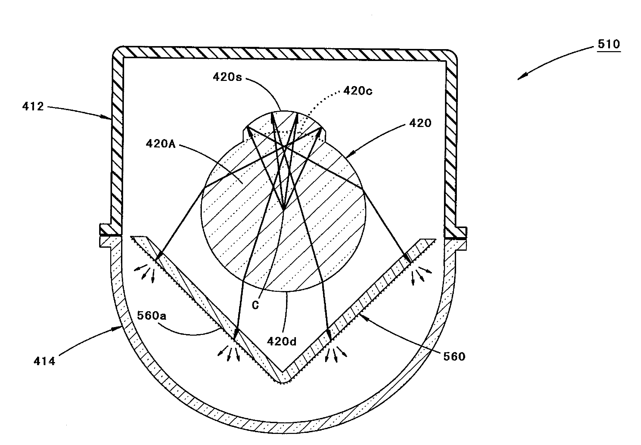
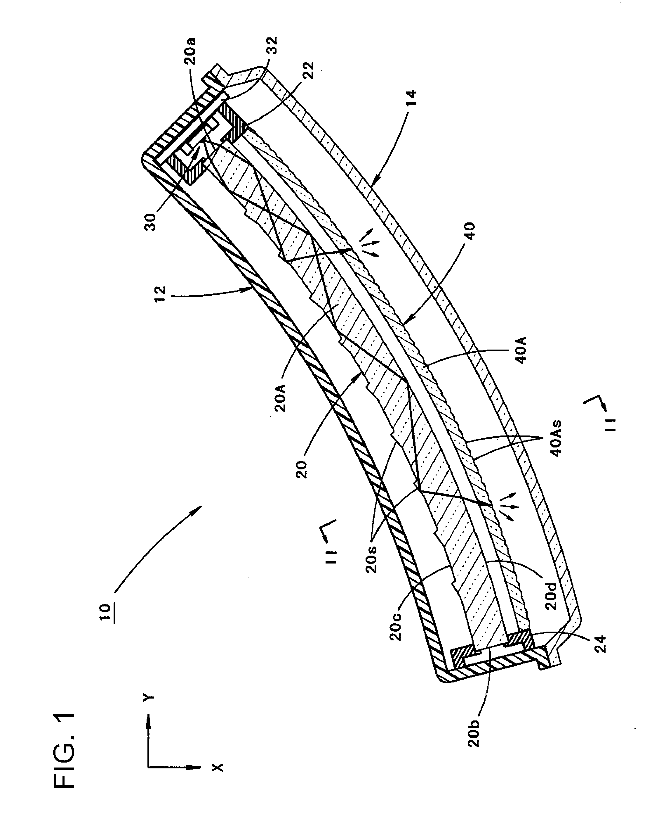
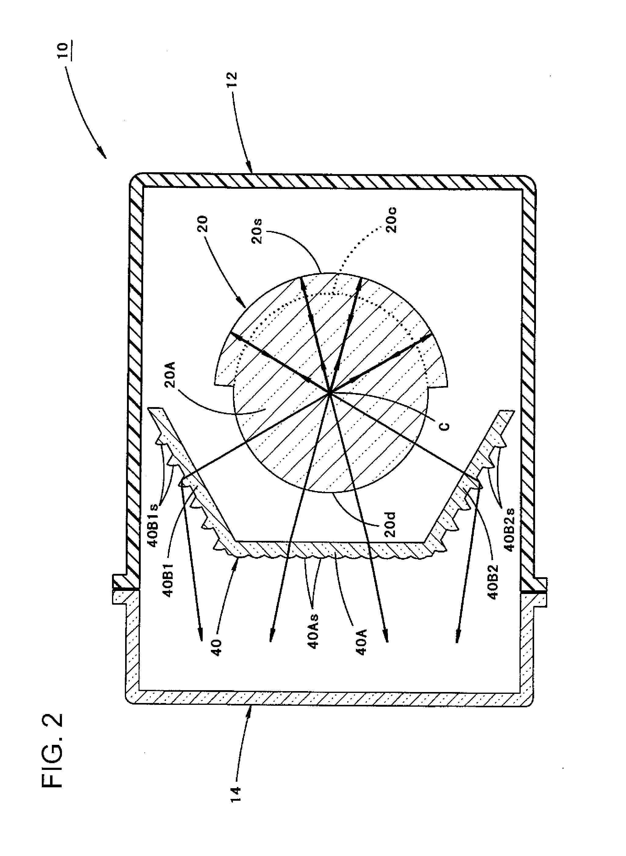
[0031]FIG. 1 is a plane cross-sectional view showing a vehicular lamp 10 according to one or more embodiments of the present invention. FIG. 2 is a sectional view taken along line II-II in FIG. 1.

[0032]As shown in these figures, the vehicular lamp 10 according to one more embodiments of the present invention is a tail lamp that is provided at the right rear end of a vehicle, and is configured so that a light guide 20 placed so as to extend in the lateral direction of the vehicle and a light source ...


PUM


Abstract

A vehicular lamp, has a light guide extending in a predetermined direction, and having an end surface located in the predetermined direction thereof, and a light source configured to cause light to be incident on the light guide from the end surface, and configured to emit the light incident from the end surface from a front surface portion of the light guide. Reflective elements that reflects the light incident on the light guide toward the front surface portion of the light guide are formed at a plurality of positions along the predetermined direction on a rear surface portion of the light guide. Each of the reflective elements is comprises a curved surface profile in a cross-section along a plane perpendicular to the predetermined direction.

Description

BACKGROUND[0001]1. Technical Field[0002]The present invention relates to vehicular lamps including a light guide.[0003]2. Description of the Related Art[0004]Conventionally, vehicular lamps are known which are configured to include a light guide placed so as to extend in a predetermined direction, and a light source placed so that light is incident on the light guide from its end surface located in the predetermined direction.[0005]“Patent Document 1” describes a configuration of such a vehicle lamp in which a reflective element that reflects incident light on the light guide toward a front surface portion of the light guide is formed at a plurality of positions along the predetermined direction on a rear surface portion of the light guide.[0006]The vehicular lamp disclosed in “Patent Document 1” is configured so that the light internally reflected by the plurality of reflective elements formed on the rear surface portion of the light guide is emitted from the front surface portion ...

Claims


Application Information

Patent Timeline
Patent Type & Authority Applications(United States)
IPC IPC(8): F21S8/10
CPCF21S48/00F21S43/27F21S43/26F21S43/237F21S43/245F21S43/247F21S43/40F21S43/00
Inventor NAKADA, ASAMI
Owner KOITO MFG CO LTD
Why Eureka
Try Eureka