
Network audio testing system and network audio testing method thereof

a network audio and testing system technology, applied in the direction of substation equipment, electrical equipment, surveillance/monitoring/testing arrangements, etc., can solve the problems of not being able to test the residual energy of the echo of the network communication system or the attenuation degree of the energy transmitting signal, and not having an objective evaluation method to distinguish the pros and cons of the network communication system regarding voice processing performan

Active Publication Date: 2014-02-06
PEGATRON
View PDF0 Cites 8 Cited by
  • Summary
  • Abstract
  • Description
  • Claims
  • Application Information

AI Technical Summary

Benefits of technology

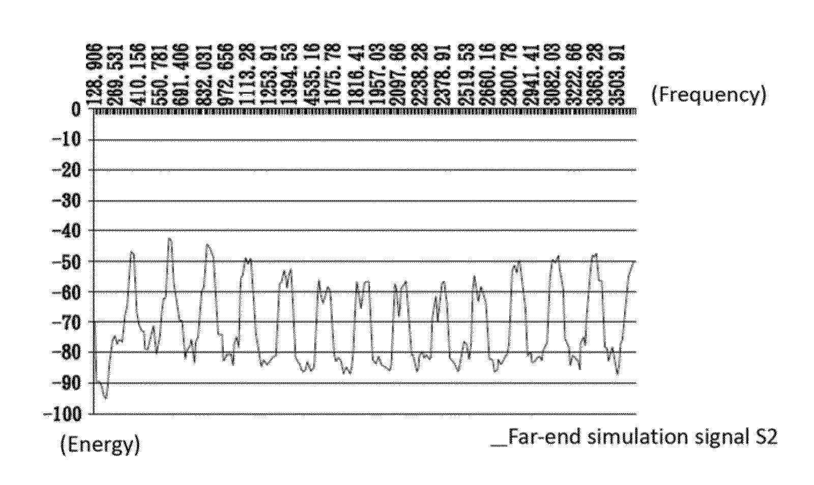
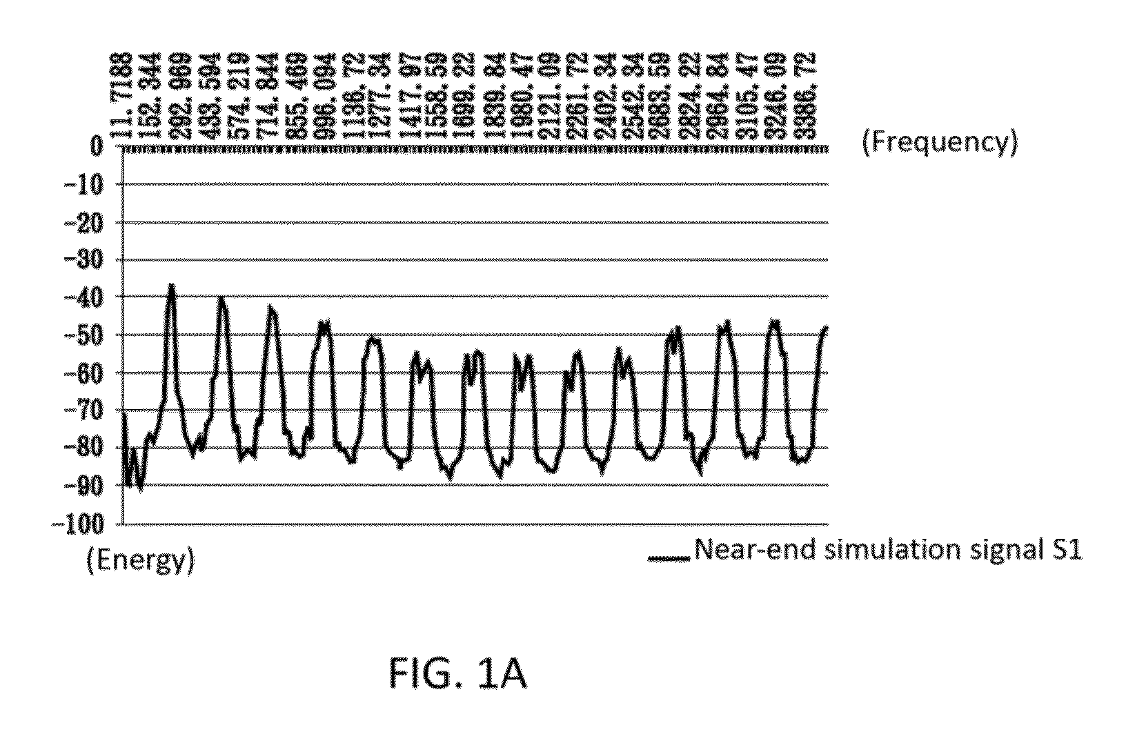
The invention is a network audio testing system that can test how well a network communication system works during communication. It includes a processing system, a sound simulation device, and a memory module. The processing system generates two signals, one with a different waveform, and the sound simulation device makes a sound like the near-end signal. The system stores the sound signal. Simultaneously, the processing system generates another signal with a different waveform and sends it through the network to the far-end device. The far-end device receives the signal and sends it back to the processing system. The processing system compares the two signals to measure the quality of the network's performance. The network audio testing method is similar. The technical effect is a system that can accurately test network communication quality.

Problems solved by technology

However, in the prior art there is no objective evaluation method to distinguish the pros and cons of the network communication systems regarding voice processing performances.
However, the test method of ITU-T P340 only records the attenuation degree of the duplex transmission.
It cannot test the residual energy of the echo of the network communication system or the attenuation degree of the energy transmitting signals.

Method used


Image

  • Network audio testing system and network audio testing method thereof
  • Network audio testing system and network audio testing method thereof
  • Network audio testing system and network audio testing method thereof

Examples


Embodiment Construction

[0018]The present invention will be apparent from the following detailed description, which proceeds with reference to the accompanying drawings, wherein the same references relate to the same elements.

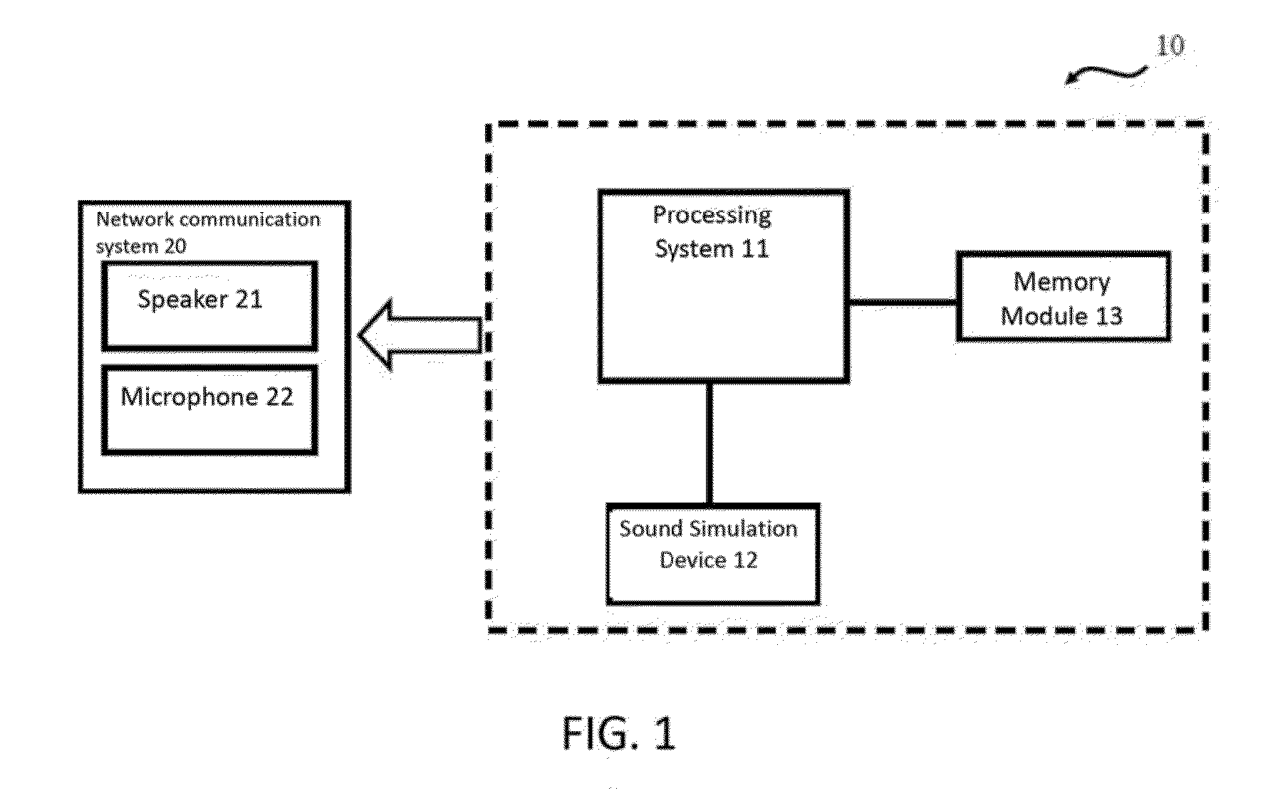
[0019]Please refer to FIG. 1, which is a schematic diagram of the architecture of the network audio testing system according to one embodiment of the invention.

[0020]The network audio testing system 10 of the embodiment is used to test the performance of a network communication system 20 during communication. The network communication system 20 may be a mobile phone, a tablet PC, a notebook computer, a network phone or any device which has voice communication functionalities. The network communication system 20 has a speaker 21 and a microphone 22 for a user to perform a voice communication with another network communication system 20 via a network environment. The network communication system 20 may have the functions of echo suppression and duplex communication quality control by AE...


PUM


Abstract

A network audio testing system and a network audio testing method thereof for testing the performance of a network communication, system during communication are disclosed. The system includes a processing system and a sound simulation device. The processing system is for generating a near-end simulation signal and a far-end simulation signal. The sound simulation device is for receiving and making a near-end simulation sound. The near-end simulation sound is received by a microphone of the network communication system to generate a first test signal. The processing system further simultaneously makes the sound simulation device sounding the near-end simulation sound and a speaker sounding a far-end simulation sound to obtain a second test signal. The processing system compares the first and the second test signal to obtain an attenuation degree of the near-end simulation signal and a residual energy of the far-end simulation signal.

Description

BACKGROUND OF THE INVENTION[0001]1. Field of Invention[0002]The invention relates to a network audio testing system and the network audio testing method thereof and, in particular, to a network audio testing system and the network audio testing method thereof that can test the performance of a network communication system during communication.[0003]2. Related Art[0004]With the progress of technology, the network speed today has become increasingly fast. Therefore, a network communication system for voice communication using a network has been widely used by users. During the two-way communication under the hands-free mode of the network communication system, a user may sometimes hear his or her own voice or cannot hear the voice of another user. Therefore the network communication systems available in the market utilize various voice signal processing solutions to reduce external noises, and each solution has its uniqueness. However, in the prior art there is no objective evaluation...

Claims


Application Information

Patent Timeline
Patent Type & Authority Applications(United States)
IPC IPC(8): H04M1/24
CPCH04M1/24H04M1/60
Inventor YANG, CHIH-KAILEE, SHUANG-AN
Owner PEGATRON
Learn More