
Eureka
For R&D, Eureka makes reading and utilizing patents & technical documents easy.
Eureka AIR
Designed for self-driven R&D workflows. Generate viable solutions, solve complex R&D challenges, empower your innovation with AI.

Eureka Materials
Designed for material experts only. Revolutionize your material R&D, from search, analyze, to developing new materials.

TechResearch
Generate reliable direction feasibility study reports for your R&D in just a few steps.

TechSeek
Discover and master advanced knowledge NOW. Basics, ideas, possibilities, all at once.

TechMind
As an expert in R&D Theories, TechMind can generates customized viable solutions instantly.

TechRisk
Analyze your overall solution with one click, know your potential R&D risks in advance.

TechMonitor
Get weekly tech updates, stay abreast of the latest tech innovations and key insights.
Electrical pump apparatus
a technology of electric pump and electric motor, which is applied in the direction of positive displacement liquid pump, piston pump, liquid fuel engine, etc., can solve the problems of entering the housing, and achieve the effect of enhancing the degree of failure detection
- Summary
- Abstract
- Description
- Claims
- Application Information
AI Technical Summary
Benefits of technology
Problems solved by technology
Method used
Image

Examples
embodiment 1
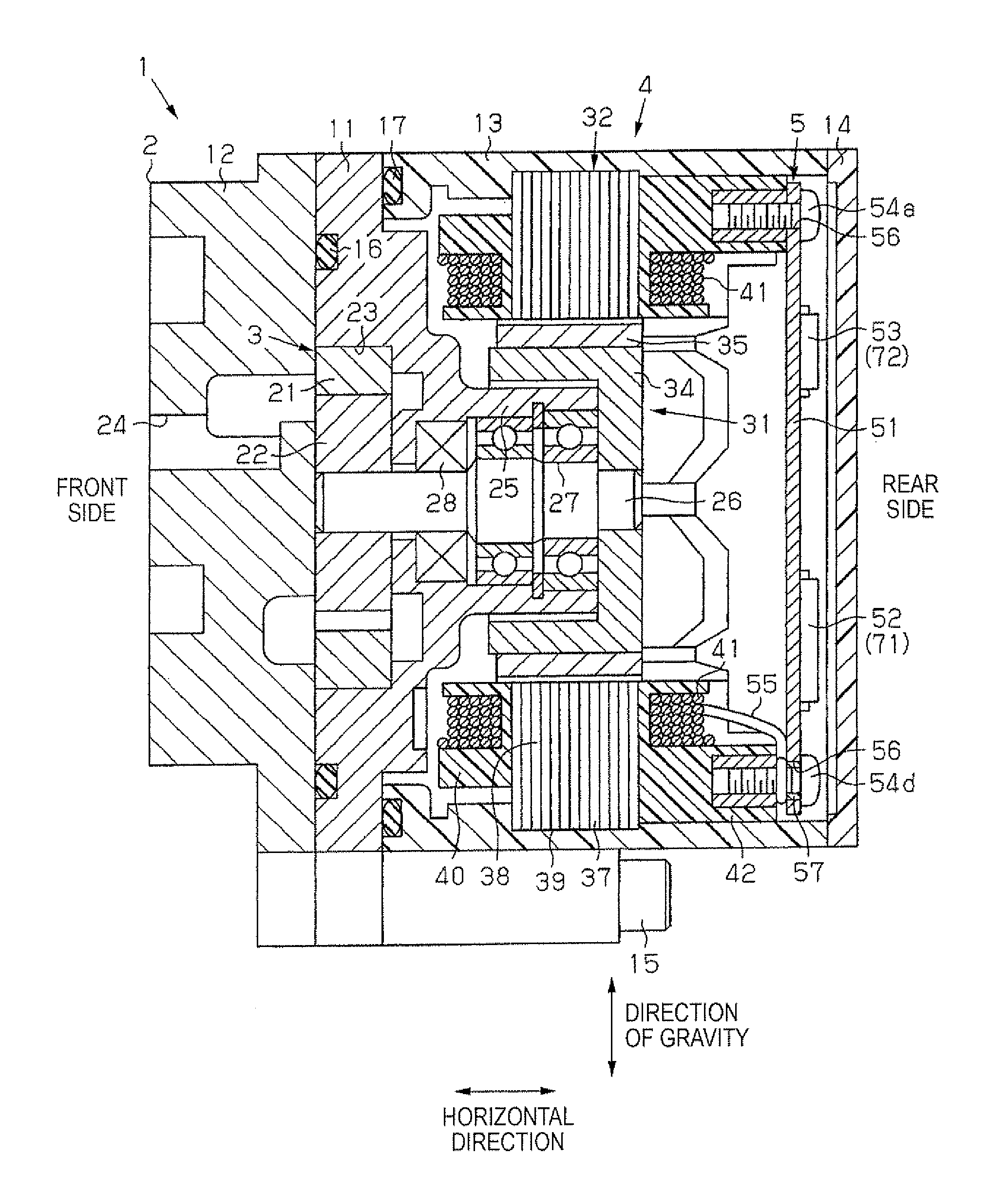
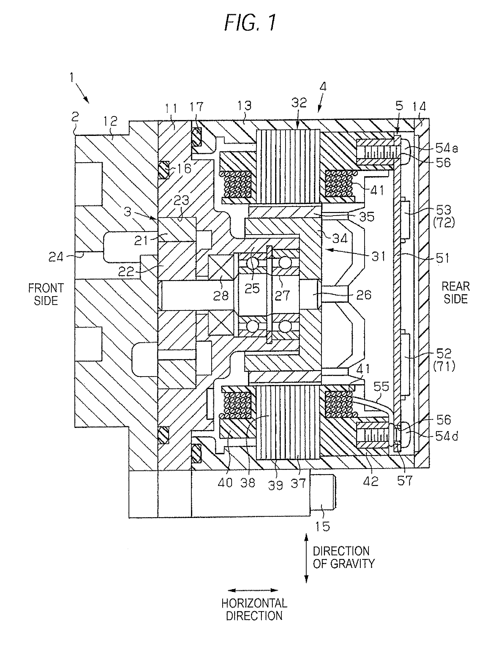
[0022]As shown in FIG. 1, an electrical pump apparatus 1 includes a housing 2 which is formed into an approximately cylindrical shape. In the housing 2, a pump 3 that generates an oil pressure, a motor 4 that drives the pump 3, and a control device 5 that controls the operation of the motor 4 are integrally housed. In the following description, a one axial end side (the left side in FIG. 1) of the housing 2 is referred to as the front side, and the other axial end side (the right side in FIG. 1) is referred to as the rear side.
[0023]The housing 2 includes: an approximately annular pump case 11; a pump plate 12 which is placed in front of the pump case 11; a cylindrical motor case 13 which is placed in rear of the pump case 11; and a cover 14 which closes a rear opening end of the motor case 13. The pump case 11 and the pump plate 12 are made of a metal material, and the motor case 13 and the cover 14 are made of a resin material. The pump case 11, the pump plate 12, and the motor ca...
embodiment 2
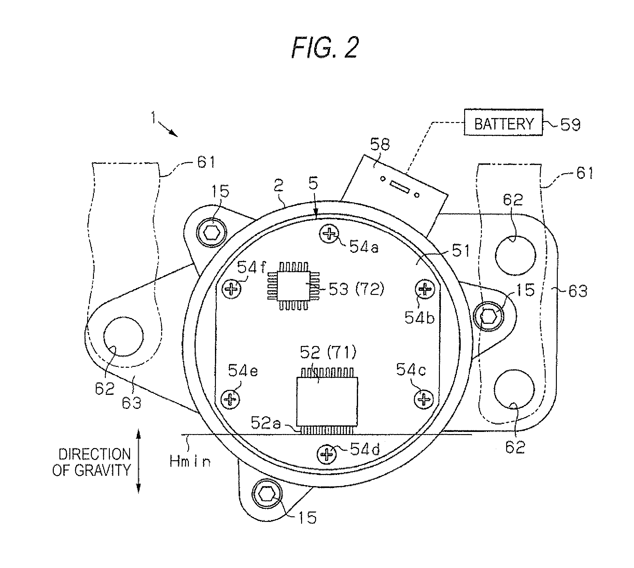
[0055]FIG. 4 shows an electrical pump apparatus of Embodiment 2. Embodiment 2 is configured similarly to Embodiment 1 except the manner of attachment of the control device 5, and therefore detailed description of the portions is omitted.
[0056]In Embodiment 2, the attaching portions are formed so that, in the state where the electrical pump apparatus 1 is attached to the vehicle body, the circuit board 51 is in the horizontal direction. The circuit board 51 is fixed to the motor case 13 and the pump case 11 through the screws 54. The control IC chip 53 is mounted on one surface of the circuit board 51, the power IC chip 52 is mounted on the other surface, and the control IC chip 53 is placed so as to be higher in the direction of gravity than the power IC chip 52. In the embodiment, the position where the plurality of terminals projecting from the power IC chip 52 is at the lowest water level Hmin. The cover 14 is fixed to the pedestal portion 42 of the motor case 13 by other bolts 6...
PUM
 Abstract
Description
Claims
Application Information
 - R&D Engineer
- R&D Manager
- IP Professional
- Industry Leading Data Capabilities
- Powerful AI technology
- Patent DNA Extraction
Browse by: Latest US Patents, China's latest patents, Technical Efficacy Thesaurus, Application Domain, Technology Topic, Popular Technical Reports.
© 2024 PatSnap. All rights reserved.Legal|Privacy policy|Modern Slavery Act Transparency Statement|Sitemap|About US| Contact US: help@patsnap.com