
Frequency converter driving embedded permanent magnet synchronous motor stator inter-turn short-circuit fault diagnosis method

A technology for permanent magnet synchronous motors and inter-turn short-circuit faults, which is applied in the direction of motor generator testing, instrumentation, and electrical measurement. Effects of salient polarity interference, wide application range, and high reliability of early fault detection

Inactive Publication Date: 2017-06-13
ZHEJIANG UNIV
View PDF11 Cites 15 Cited by
  • Summary
  • Abstract
  • Description
  • Claims
  • Application Information

AI Technical Summary

Problems solved by technology

However, due to the obvious rotor saliency of the embedded permanent magnet motor, the fault characteristic frequency is scattered and the amplitude is reduced, which increases the difficulty of fault detection
At the same time, due to the lack of an embedded permanent magnet motor fault model in the switching frequency band, it is difficult to achieve the unity of fault indicators under various working conditions in variable frequency speed regulation

Method used


Image

  • Frequency converter driving embedded permanent magnet synchronous motor stator inter-turn short-circuit fault diagnosis method
  • Frequency converter driving embedded permanent magnet synchronous motor stator inter-turn short-circuit fault diagnosis method
  • Frequency converter driving embedded permanent magnet synchronous motor stator inter-turn short-circuit fault diagnosis method

Examples


Embodiment 1

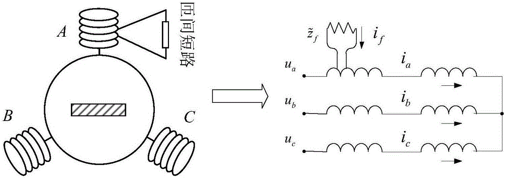
[0036] In this embodiment, a 15kW three-phase embedded permanent magnet motor with inter-turn short circuit in phase A is taken as an example to derive a general fault calculation model for high-frequency excitation.

[0037] The common permanent magnet motor d, q axis model can be described as:

[0038]

[0039] Among them, u d , u q Indicates d, q axis voltage, i d i q Indicates d, q axis current, R d , R q Respectively d, q axis stator resistance, L d , L q Indicates d, q axis stator inductance, ω r Indicates the angular frequency of rotor rotation, ψ m Represents the flux linkage amplitude of the permanent magnet, and p=d / dt represents the time differential operator.

[0040] When the motor is under high-frequency excitation, the ω contained in (1) can be ignored r item and copper consumption resistance, considering the steady-state situation, the time differential operator can be replaced by p=jω h ,Have:

[0041]

[0042] Among them, j is the unit of the ...

Embodiment 2

[0067] In this embodiment, a 15kW embedded permanent magnet motor control system for electric vehicles is taken as an example, and the common sine wave PWM is selected as the inverter modulation method, and the expression structure of the excitation voltage is given.

[0068] According to the binary Fourier series, the phase voltage waveform expression of the inverter relative to the midpoint of the bus voltage can be obtained as:

[0069]

[0070] Among them, u PWM modulation voltage for the inverter, θ c is the carrier phase angle, θ 1 is the modulation wave phase angle, A m,n , B m,n are the corresponding sine and cosine coefficients, and the subscripts m and n are the harmonic indices of the carrier wave and the modulation wave respectively.

[0071] Carrier phase angle θ in formula (12) c , Modulating wave phase angle θ 1 Both are functions of time, which can be described as the following relationship:

[0072]

[0073] Among them, ω c is the carrier angular...

Embodiment 3

[0094] The steps of the fault diagnosis method for the turn-to-turn short circuit of the embedded permanent magnet motor driven by the frequency converter are as follows:

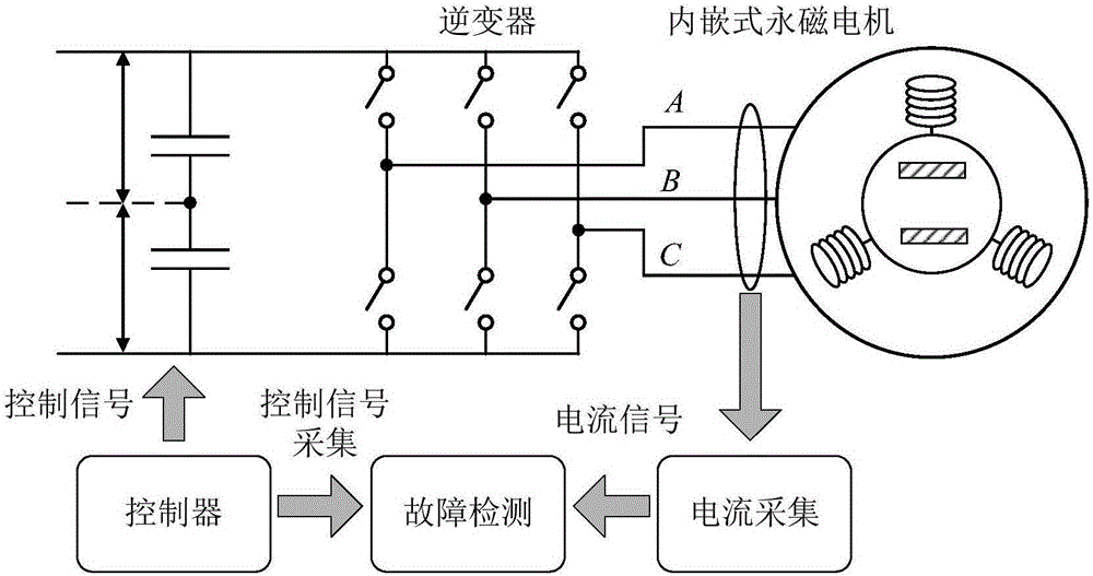
[0095] (1) if figure 2 As shown, the three-phase current i of the embedded permanent magnet motor is collected a i b i c . Set the sampling frequency to f s=500kHz, satisfy f s >6f c , f c =4kHz is the inverter carrier frequency. The pre-filter cut-off frequency is 50kHz to meet the requirements greater than 3f c , less than f s The Nyquist frequency of . The length of time is NT s =1s, N is the total number of sampling points, T s =2×10 -6 s is the sampling step size.

[0096] (2) if figure 2 As shown, the controller signal is collected, including the modulation ratio signal M, the DC bus voltage u dc , synchronization signal s α =cosθ r , s β = sinθ r , θ r is the rotor angle. Set the sampling frequency to f s =500kHz, satisfy f s >6f c , f c =4kHz is the inverter carrier frequ...


PUM


Abstract

The invention discloses a frequency converter driving embedded permanent magnet motor stator inter-turn short-circuit fault diagnosis method. According to the method, a current signal of an operating motor and an inside signal of a controller are used for realizing inter-turn short-circuit fault detection and degree judgment. The method comprises the flowing steps of firstly, a proper inverter switch signal is selected to be used as a detecting excitation source; the injection of an additional high-frequency signal is not needed; the additional loss caused by a high-frequency injection detecting method is avoided; meanwhile, the early fault detection reliability is enhanced; secondly, three-phase current is subjected to rotational coordinate conversion; the switching current harmonic in a three-phase coordinate system is converted under a rotary coordinate system; the saliency interference factor of the motor is effectively decoupled; finally, a frequency domain multipoint interpolation extraction algorithm is used, and multi-fault feature information is comprehensively used, so that the influence of noise interference and frequency spectrum leakage on the detection result is effectively avoided. The method has the advantages that the application range is wide; the fault detection effect is good; the recognition precision is high; the stator inter-turn short-circuit fault can be diagnosed in real time, and the fault degree index is given.

Description

technical field [0001] The invention relates to the technical field of fault diagnosis, in particular to a method for diagnosing a short-circuit fault between turns of an embedded permanent magnet motor stator. Background technique [0002] With the increasing demand for high power density and high torque energy conversion equipment in the industrial field, the application of permanent magnet synchronous motors is gradually increasing. Due to the introduction of rare earth permanent magnets, this type of motor has a higher power density, and the output torque capability can be improved under the same volume. At the same time, the embedded structure has obvious rotor saliency, which can further increase the output torque capability. In addition, this type of motor has the advantages of good dynamic performance and easy control. Applications including locomotive traction, wind power generation equipment, and industrial machine tool automation have used this type of motor in ...

Claims


Application Information

Patent Timeline
Patent Type & Authority Applications(China)
IPC IPC(8): G01R31/02G01R31/34
CPCG01R31/343G01R31/50
Inventor 黄进刘赫叶明
Owner ZHEJIANG UNIV
Learn More