Resilient pressing member structure

a pressing member and resilient technology, applied in the direction of emergency actuators, electrical appliances, operation facilitation, etc., can solve the problems of reducing the light flux in the common backlighting keyboard, affecting the product's backlight brightness, so as to improve the backlight brightness and improve the product's brightness. , the effect of reducing the cost of extra parts

Inactive Publication Date: 2014-02-13
LITE ON ELECTRONICS (GUANGZHOU) LTD +1
View PDF6 Cites 12 Cited by
  • Summary
  • Abstract
  • Description
  • Claims
  • Application Information

AI Technical Summary

Benefits of technology

[0012]In summary, the instant disclosure of the resilient pressing member structure provides the end users' with a better and clearer display for pressing member functions under any environment with inadequate lighting. Secondly, the instant disclosure can replace the function of the detached large-ranged light guiding board and film for pressing member backlighting, thus significantly increases the product's backlight brightness, lower cost from extra parts, and hence increases the competitiveness of the product. Furthermore, the cavity of the pressing members is filled one of the following fluids: a gas or a liquid. The pressing members are in turn equipped with cushioning and pressure dissipating functionality, thus prevents end users from finger fatigue and increase comfort for prolong usage. Furthermore, the instant disclosure also offers noise reduction effect by reducing the sound generated during pressing member strokes.

Problems solved by technology

As a result, the release of an illuminated keyboard which visually attracts end users' attention hence heightens the chances of sales.
However, excess cost is also induced with the large-ranged board.
Furthermore, due to the light guiding board and film being disposed beneath the electrical signal thin-film layer, light flux in the common backlighting keyboards is dramatically diminished.
Consequently, insufficient light is diffused through the keys, and renders poor illumination.

Method used


Image

  • Resilient pressing member structure
  • Resilient pressing member structure
  • Resilient pressing member structure

Examples


Embodiment Construction

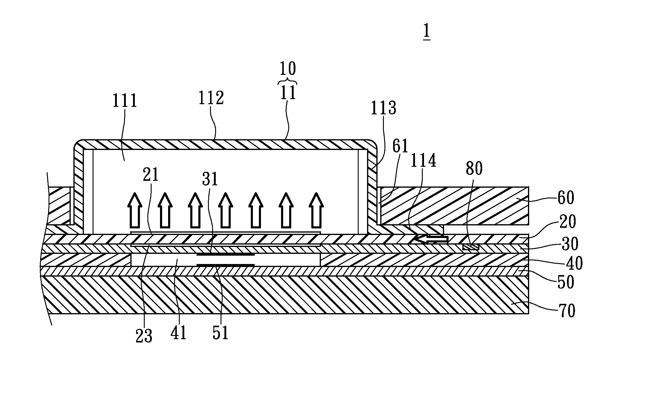
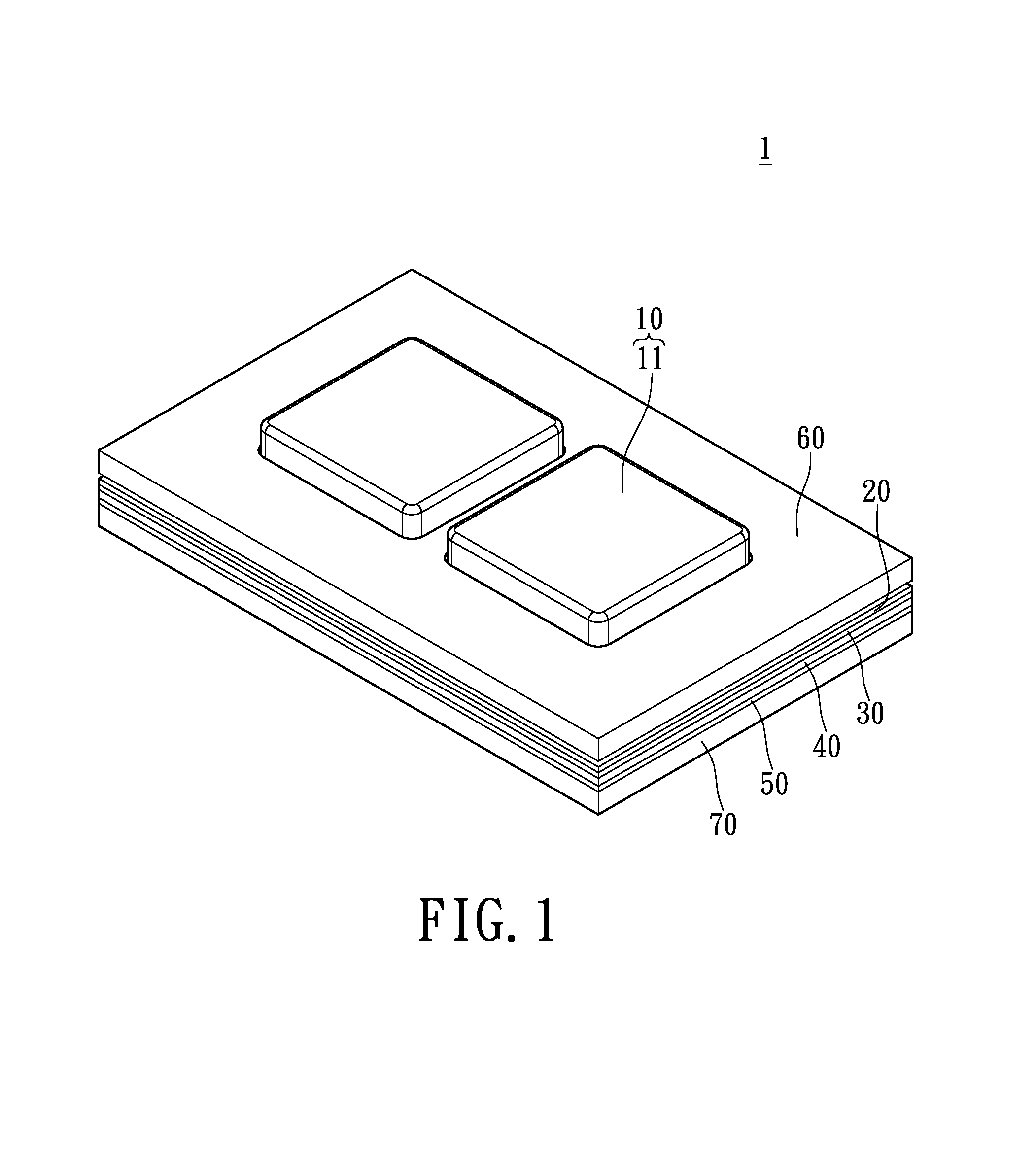
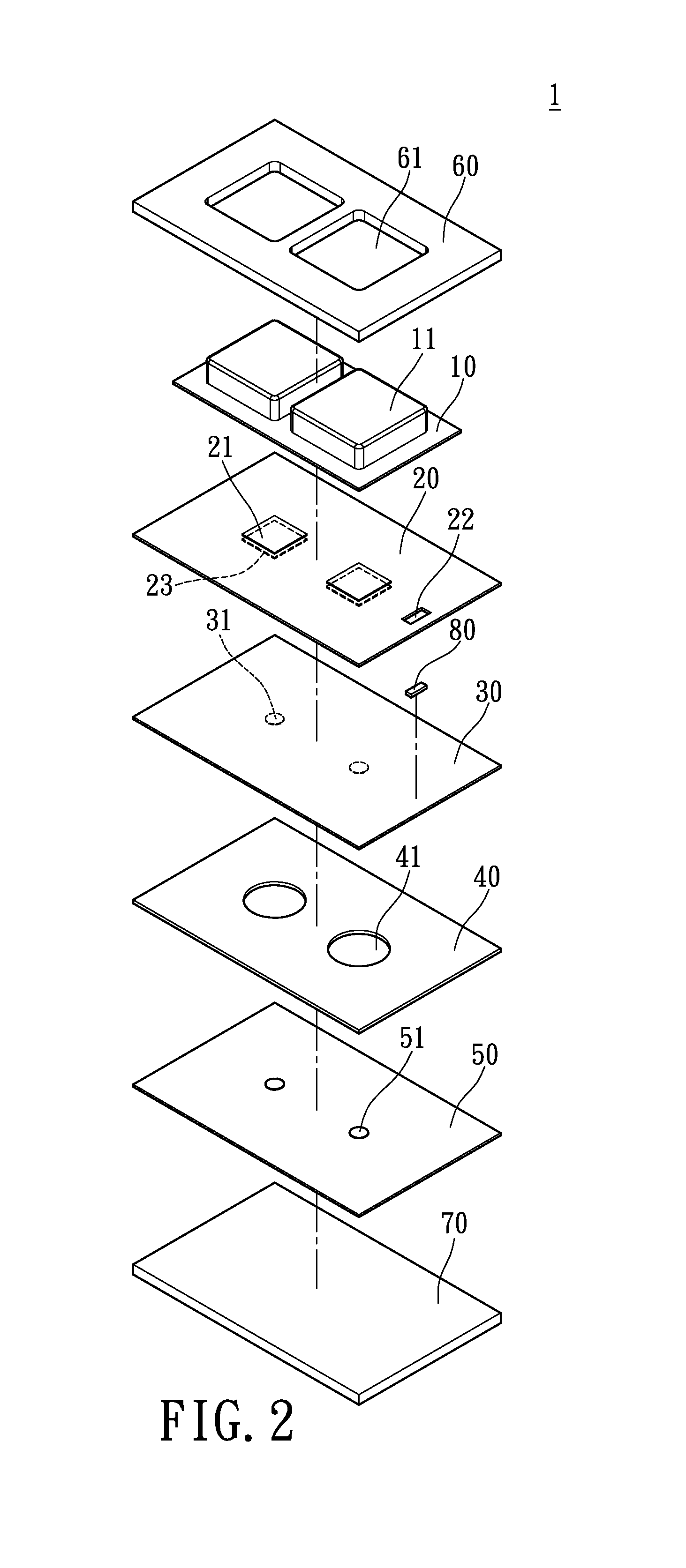
[0021]FIG. 1 and FIG. 2 illustrate an isometric view and an exploded view of a resilient pressing member structure 1 in accordance with an embodiment of the instant disclosure. The resilient pressing member structure 1 in FIG. 1 comprised of a upper cover 60, a pressing unit 10, a translucent insulated layer 20 that comprises at least one light guiding structure 21 disposed on the topside thereof and a light reflecting structure 23 disposed on the bottom-side thereof in correspondence to the light guiding structure 21, a first conductive layer 30, a spacer 40, a second conductive layer 50, and may further include a base plate 70.

[0022]FIG. 3 illustrates a cross-sectional view of the resilient structure 1. The pressing unit 10 is arranged on a top-side (i.e., the user-facing side) of the translucent insulated layer 20. The pressing unit 10 comprises a plurality of pressing members 11, which are integrally formed on the pressing unit 10 by suitable means including molding. Suitable ma...


PUM


Abstract

The instant disclosure is a resilient pressing member structure having a pressing unit disposed on top of a translucent insulated layer, an upper cover, a light-emitting unit, two conductive layers and a spacer. The pressing unit includes a plurality of pressing members while the cover is formed with a cavity filled with a fluid to achieve the effect of pressure dispersion. A light guiding structure and a light reflecting structure are disposed on the topside and the backside of the insulated layer, respectively. The insulated layer is formed by at least one light unit opening which extends through the insulated layer. The light-emitting unit is hosted inside the light unit opening. Light from the light-emitting unit penetrates the insulated layer and reaches the pressing member. Then the guiding structure directs light while the reflecting structure reflects light towards the pressing member, thus illuminates the pressing member.

Description

BACKGROUND OF THE INVENTION[0001]1. Field of the Invention[0002]The instant disclosure relates to a pressing member structure; in particular, to a resilient pressing member structure which can enhance pressing member identification and convenience under conditions of deficient lighting. Furthermore, the instant disclosure provides a backlight pressing member structure capable of achieving low weight and reduced cost.[0003]2. Description of Related Art[0004]As the design of keyboard becoming more and more diverse in the market, not only is the input function essential to a keyboard, the visual effects of the keys are becoming more and more valued by the end users. As a result, the release of an illuminated keyboard which visually attracts end users' attention hence heightens the chances of sales. On a more practical note, the keyboard illuminates at night as well as environments with inadequate lighting, specifically by illuminating symbols, numbers, and text on the keys, thus improv...

Claims


Application Information

Patent Timeline
Patent Type & Authority Applications(United States)
IPC IPC(8): H01H13/83
CPCH01H13/83H01H13/84H01H2217/016H01H2217/044H01H2219/044H01H2219/056H01H2219/06H01H2219/062H01H2221/062H01H2221/064H01H2227/03
Inventor LEE, CHIEN-HSIN
Owner LITE ON ELECTRONICS (GUANGZHOU) LTD
Why Eureka
Try Eureka